Non-contact potentiometer

Active Publication Date: 2016-02-11
MULTIDIMENSION TECH CO LTD
View PDF3 Cites 5 Cited by
  • Summary
  • Abstract
  • Description
  • Claims
  • Application Information

AI Technical Summary

Benefits of technology

[0021]The present invention provides a non-contact precision potentiometer with good performance, low power loss, and low cost, and it can be f

Problems solved by technology

However, long term use is complicated by contact corrosion, physical wear and tear, and loose wires; such that a potentiometer using mechanical components for a third terminal will show degraded electrical performance over time.
Unfortunately, the wear mechanism i

Method used


Image

  • Non-contact potentiometer
  • Non-contact potentiometer
  • Non-contact potentiometer

Examples


Example

Example 1

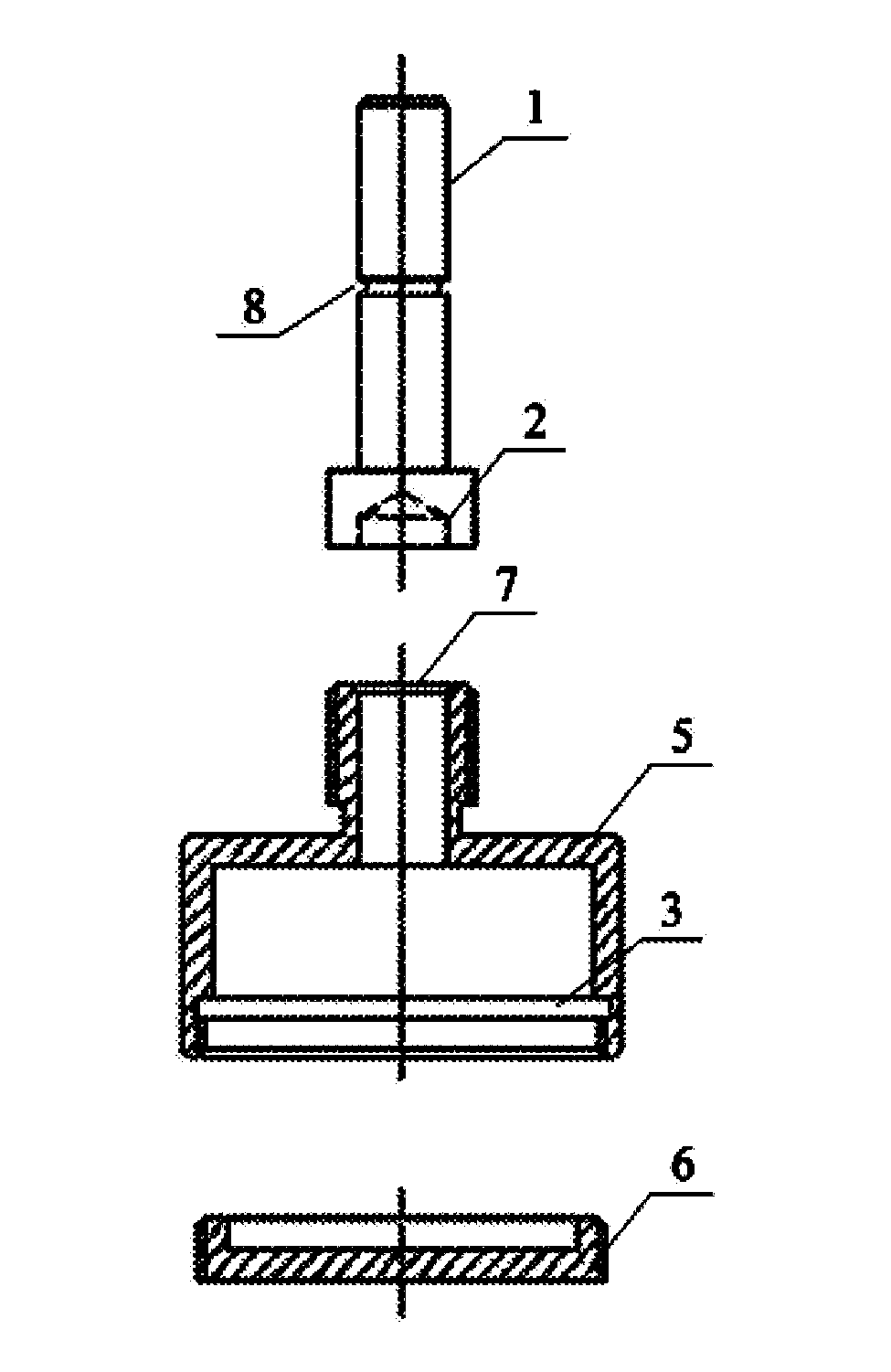
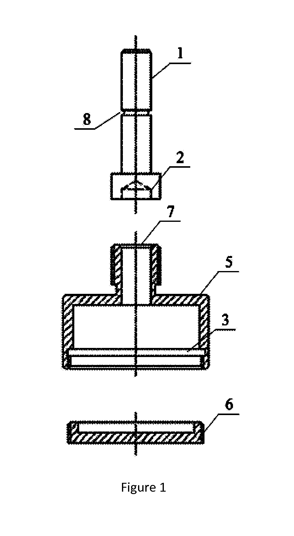
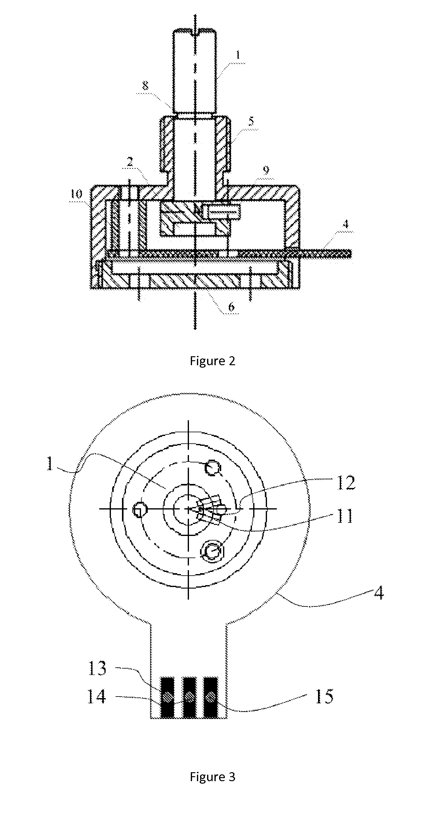
[0038]FIGS. 1 and 2, present an embodiment of the present invention that provides a non-contact type potentiometer including a rotatable shaft 1, a permanent magnet 2, a sensor chip 3, a printed circuit board (PCB) 4, a housing 5, a cover 6, and a control circuit module. Housing 5 has a convex shape, hollow inside, with a bottom opening. The top of housing 5 is provided with a through-hole 7. The rotating shaft 1 is provided with a central recess 8, and a rotating shaft has a bottom cavity 9. Permanent magnet 2 is placed on the rotating shaft 1 in the cavity 9, such that the permanent magnet 2 can be rotated with the rotating shaft 1. In this embodiment, the permanent magnet 2 may be disc-shaped. The rotating shaft 1 is placed through hole 7 in housing 5, the rotating shaft is fixed in the middle of through-hole 7 using groove 8, such that rotation of the lever 1 may be rotated relative to the base 5. The portion of the rotating shaft 1 with cavity 9 is below the groove 8 a...

Example

Example 2

[0053]FIG. 15 shows an alternative embodiment of a non-contact potentiometer distinct from example 1 in the following manner: cover plate 6 is equipped with two connecting posts 10, and printed circuit board 4 is fixed to connecting posts 10, otherwise, the design is the same as that in example 1.

[0054]It should be understood that the above detailed description of the technical implementation of the present invention of the preferred embodiments are meant to be illustrative but not restrictive. A person of ordinary skill in the art upon reading the present specification can modify the embodiments, or to some technical features equivalent replacements, based on the technical solutions described herein; and such modifications or replacements of the appropriate technical solutions of the various embodiments of the present invention do not depart from the spirit and scope of the present invention.


PUM


Abstract

The present invention relates to a non-contact potentiometer. The non-contact potentiometer comprises the following parts: a mechanical housing with through-holes; a rotating shaft comprising a top end and a magnet end on which a permanent magnet is fixed and external torque can be applied to the top end, thus driving the rotating shaft and the permanent magnet to rotate around a rotation axis and relative to the housing; a magnetoresistive sensor assembly fixed inside the housing, comprising one or more sensor chips, the sensitivity axis of the sensor chips lies in a sensing plane that is perpendicular to the axis of the rotating shaft, and separated from the permanent magnet by a predetermined distance in the direction parallel to the axis of the rotating shaft, said sensors are used for sensing the magnetic variation produced as the permanent magnet rotates with the rotating shaft thereby generating sensing signals; and three electrical connection terminals, namely a ground terminal, a power terminal, and a signal output terminal. This non-contact potentiometer has the advantages of high precision, low power consumption, and low cost. Additionally, it converts the complex analogue signal from the magnetic sensor into a standard digital format that is easy to use.

Description

TECHNICAL FIELD[0001]The present invention relates to the technical field of potentiometers, and more particularly to a non-contact potentiometer capable of converting mechanical movement into an electrical signal.BACKGROUND TECHNOLOGY[0002]In the prior art, potentiometers typically include three terminals, two of the terminals are fixed, and the remaining terminal can be moved. The moving terminal of a potentiometer is often called the third terminal. The range of the electrical signal output from the third terminal of a potentiometer is controlled by the input electrical signal potentiometer. A potentiometer's input electrical signal is typically either a voltage difference or a current provided by a source.[0003]In one embodiment of a prior art potentiometer, the potentiometer comprises a cylinder, uniformly wound with a single layer wire, the cylinder side is exposed, the top and bottom of the cylinder are each provided with a terminal, the input voltage to the potentiometer is ...

Claims


Application Information

Patent Timeline
IPC IPC(8): G01D5/16
CPCG01D5/16G01D5/145
Inventor WANG, JUNYUNWANG, FENGCHENG, XIAOFENGDAI, YULIN
Owner MULTIDIMENSION TECH CO LTD
Why Eureka
Try Eureka