Airborne hyperspectral scanning system with reflective telecentric relay
- Summary
- Abstract
- Description
- Claims
- Application Information
AI Technical Summary
Benefits of technology
Problems solved by technology
Method used
Image

Examples
Embodiment Construction
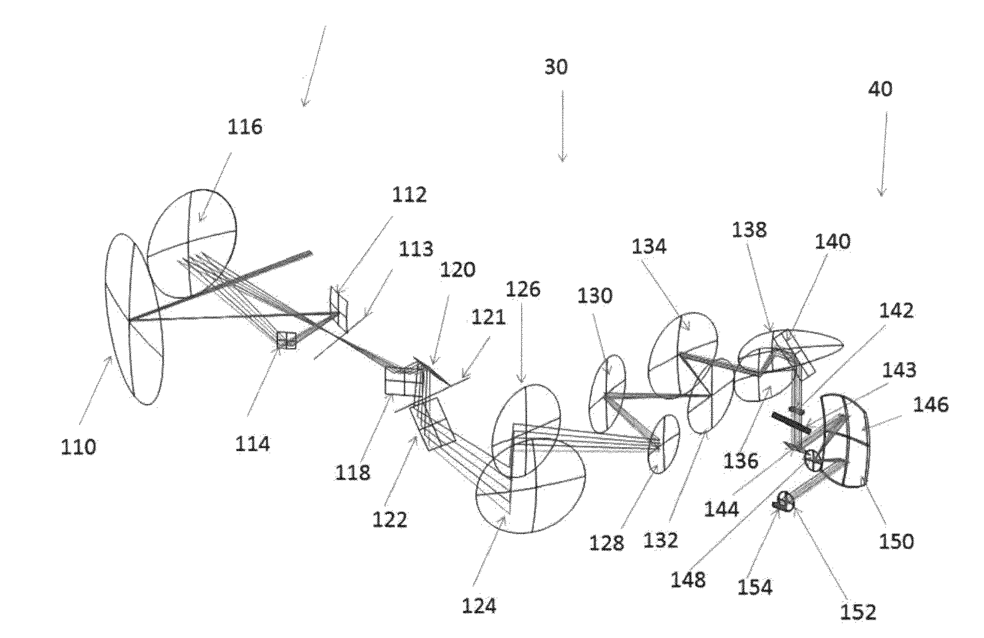
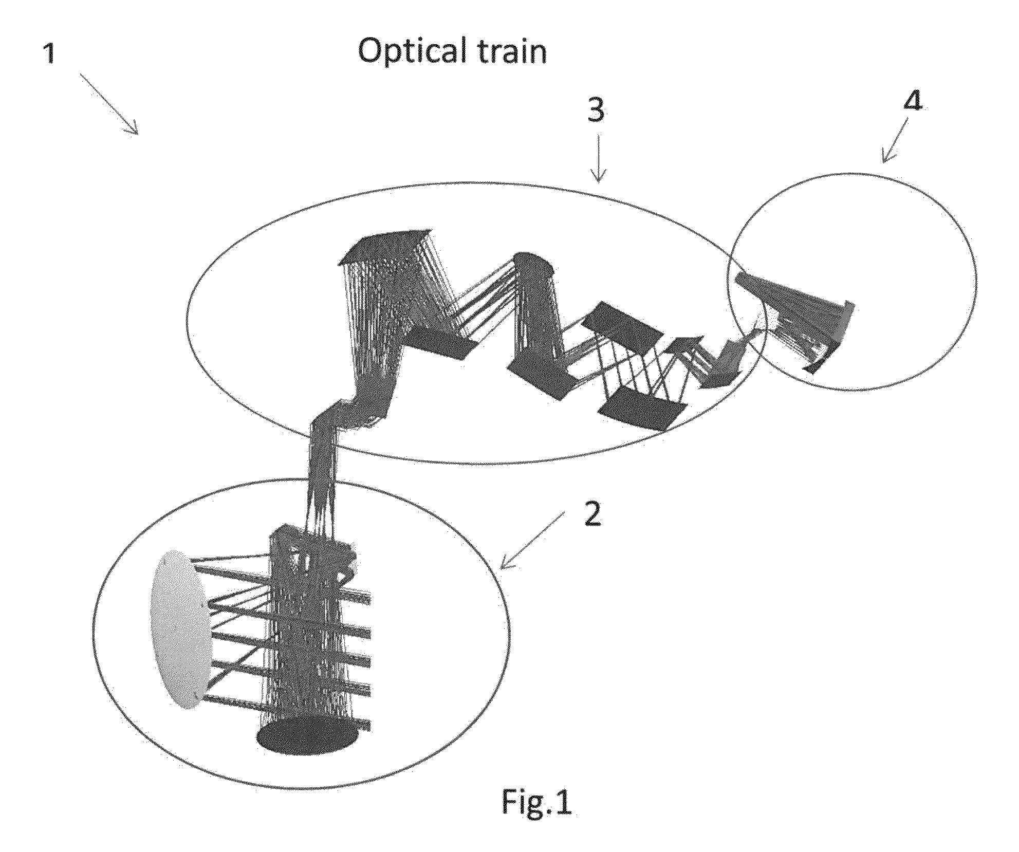
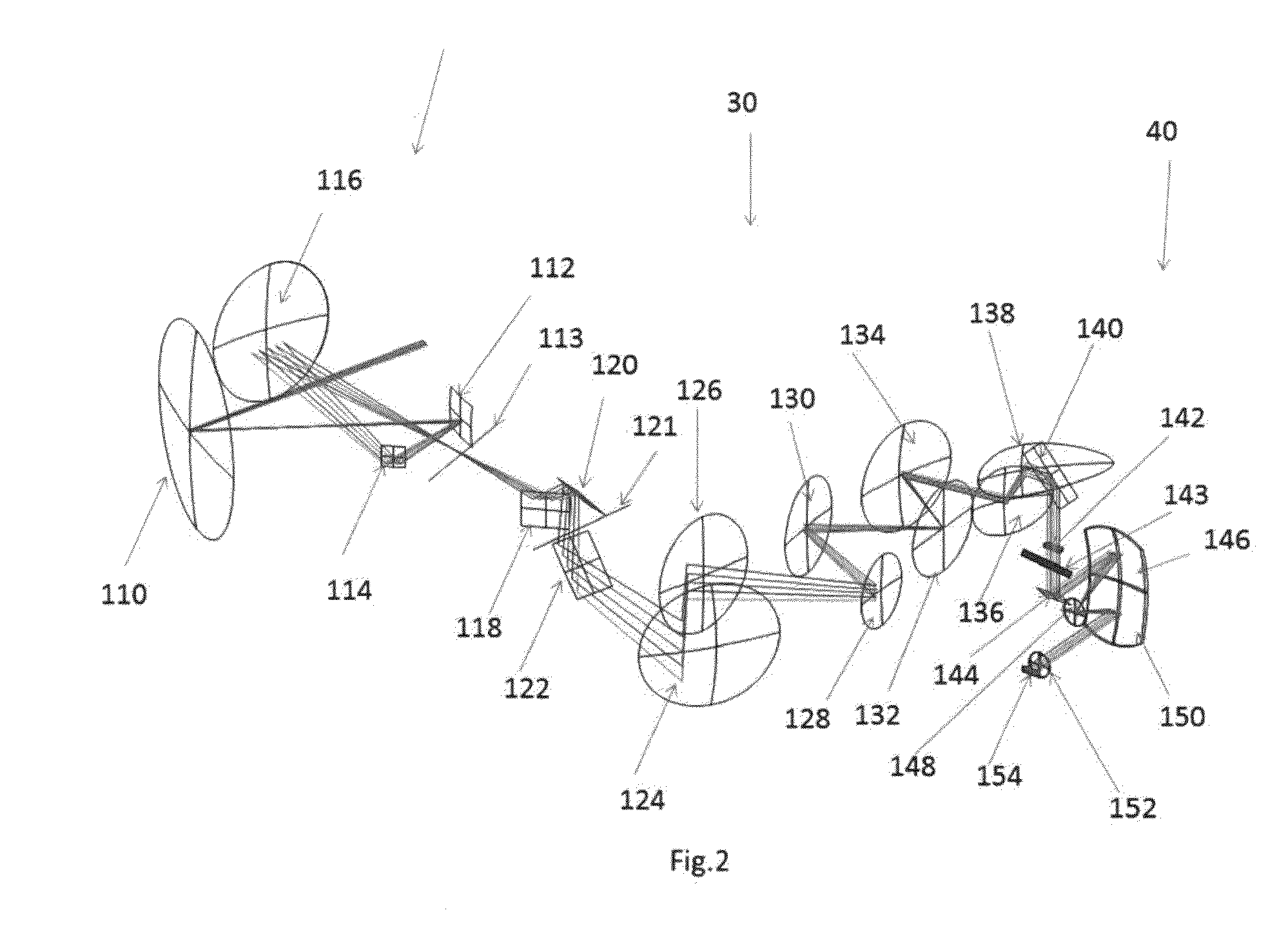
[0031]Turning to FIG. 1, the preferred embodiment of an airborne hyperspectral scanning system with reflective telecentric relay according to the invention, system 10, is generally comprises of fore-optics 20, a reflective telecentric relay 30 and Offner imaging spectrometer 40. The spectrometer assembly may include focal plane array. All of them are assembled, aligned and contained within the existing deployed in a field housing (not shown in FIG. 1). Preferably, fore-optics 20 represents three-mirror anastigmat (TMA). Reflective telecentric relay assembly 30 output is telecentric at the slit before the spectrometer. Offner imaging spectrometer 40 is doubly telecentric so that the final image size will not change with an axial position of either the slit or the focal plane array. This enables constant spectral sampling regardless of the slit and focal position. A constant and known spectral sampling is necessary to identify an object via its spectral components. In addition, telece...
PUM
 Abstract
Description
Claims
Application Information
 - R&D
- Intellectual Property
- Life Sciences
- Materials
- Tech Scout
- Unparalleled Data Quality
- Higher Quality Content
- 60% Fewer Hallucinations
Browse by: Latest US Patents, China's latest patents, Technical Efficacy Thesaurus, Application Domain, Technology Topic, Popular Technical Reports.
© 2025 PatSnap. All rights reserved.Legal|Privacy policy|Modern Slavery Act Transparency Statement|Sitemap|About US| Contact US: help@patsnap.com