Integrated circuit with distributed clock tampering detectors

a detector and integrated circuit technology, applied in the field of integrated circuits with distributed clock tampering detectors, can solve problems such as vulnerability of proposed security strategies, and achieve the effect of improving protection coverage and being immune to neutralization attempts

Active Publication Date: 2016-02-11
EM MICROELECTRONIC-MARIN
View PDF7 Cites 2 Cited by
  • Summary
  • Abstract
  • Description
  • Claims
  • Application Information

AI Technical Summary

Benefits of technology

[0020]The main purpose of invention is to rethink the integration of clock detectors into secure IC d

Problems solved by technology

However the proposed security strategy is vul

Method used


Image

  • Integrated circuit with distributed clock tampering detectors
  • Integrated circuit with distributed clock tampering detectors
  • Integrated circuit with distributed clock tampering detectors

Examples


Embodiment Construction

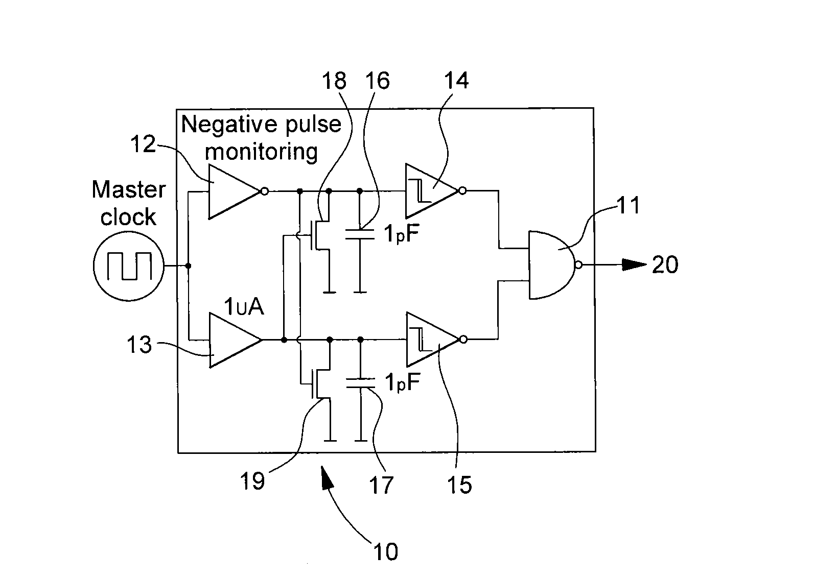
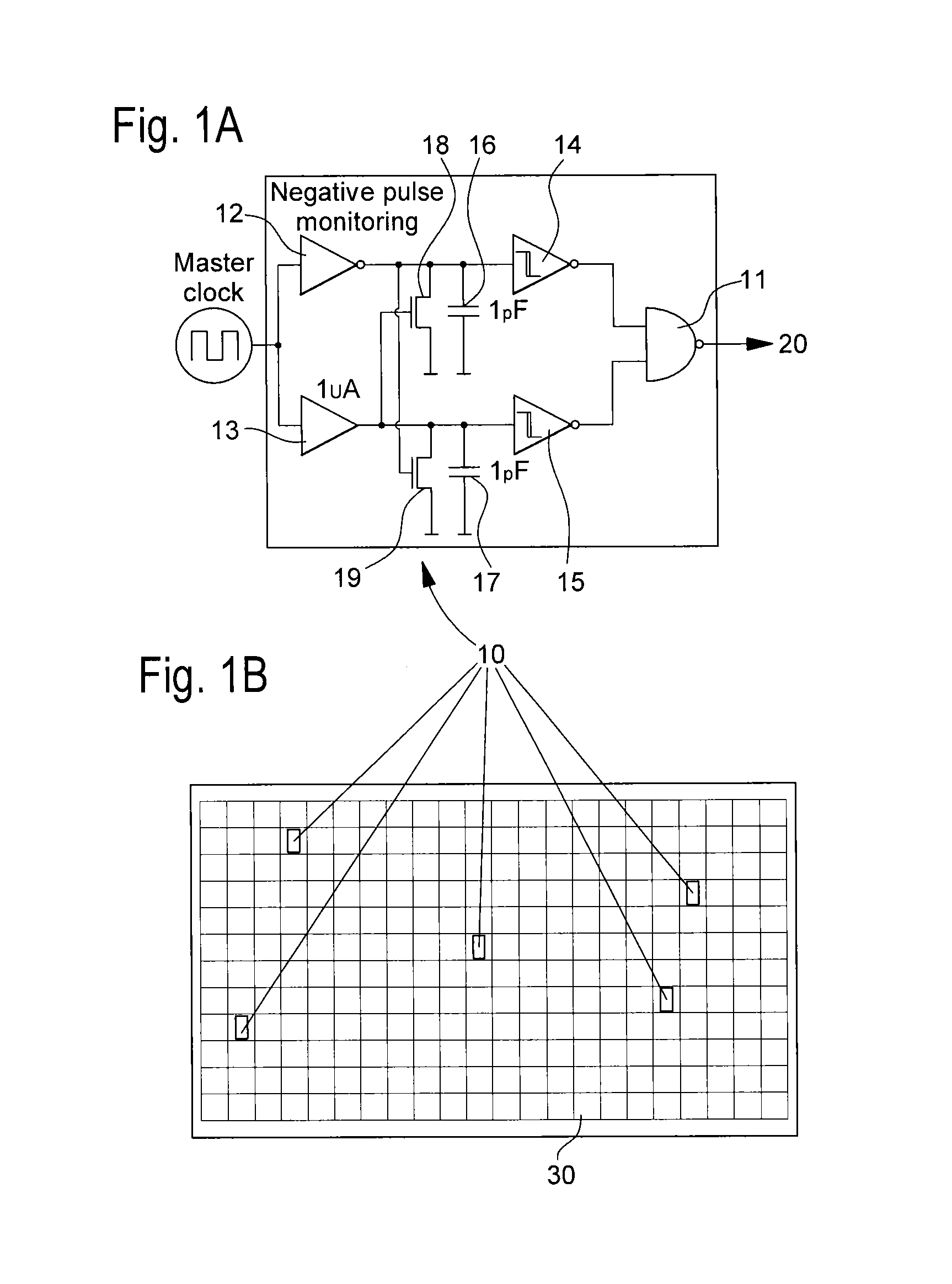
[0044]Reference is made to FIG. 1a which depicts a block diagram of a clock detector 10 being based on two mono-flops 12, 13 detecting under frequency conditions, for example 12 monitors clock low state duration and the other mono-flop 13 monitors one clock high state duration. In case clock low state duration is longer than the mono-flop delay of mono-flop 12—together with node full discharge transistor 18—and an alarm event is generated by Schmitt trigger 14 and propagated to output 20 through gate 11, which is for example a NAND gate. In case clock high state duration is longer than mono-flop delay of mono-flop 13—together with node full discharge transistor 19—an alarm event is generated by Schmitt trigger 15 and propagated to output 20 through gate 11.

[0045]The mono-flop delay is defined by buffer output drive capability and integrated C capacitor values 16 and 17 respectively for clock low duration state and clock high duration state. By this manner the clock detector 10 can m...


PUM


Abstract

A circuit configuration for secure application includes several internal frequency detectors arranged in digital units at critical points of an integrated circuit. The clock detectors are concealed in the digital part of the integrated circuit each as a standard cell (flip-flop unit) in order to prevent any external manipulation and in order to hide its function. The clock detectors are preferably disposed in a clock tree topology, which can be at several levels for distributing the clock signal through the different digital unit tree at critical points. Alarms are generated via a clock detector network if at any level an external clock attack has been monitored.

Description

[0001]This application claims priority from European patent application No. 14180234.8 filed Aug. 7, 2014, the entire disclosure of which is hereby incorporated herein by reference.TECHNICAL FIELD[0002]The present invention relates to a circuit configuration for detecting external manipulation of the clock in an integrated circuit. The integrated circuit comprises digital units and at least one clock detector monitoring frequency and duty cycle parameters of a clock signal. In case of a deviation of either frequency or of a duty cycle parameter an alarm signal can be generated at the output of said at least one clock detector.[0003]The present invention further relates to a method for detecting an external manipulation of the clock in a circuit configuration.BACKGROUND OF THE INVENTION[0004]Integrated circuits developed for secure application usually embed internal frequency detector to prevent from external manipulation of the internal clock using probing techniques. Main threat ad...

Claims


Application Information

Patent Timeline
IPC IPC(8): G01R31/317H03K19/003
CPCG01R31/31727G01R31/31719H03K19/003G06F21/554
Inventor WALTER, FABRICE
Owner EM MICROELECTRONIC-MARIN
Why Eureka
Try Eureka