Distributed Omni-Dual-Band Antenna System for a Wi-Fi Access Point

a wi-fi access point and omni-dual-band technology, applied in the field of antenna systems, can solve the problems of reducing throughput, limiting the total throughput available, and reducing throughput, so as to increase the isolation between the antennas, reduce the isolation of any antenna element in the array, and reduce the isolation

Active Publication Date: 2016-02-11
CAMBIUM NETWORKS
View PDF1 Cites 131 Cited by
  • Summary
  • Abstract
  • Description
  • Claims
  • Application Information

AI Technical Summary

Benefits of technology

[0017]In view of the above, a distributed broadband omni-dual-band antenna system for use in a Wi-Fi access point (AP) is described. The distributed broadband omni-dual-band antenna system may include an antenna array that includes 4, 6, or 8 antennas arranged in a circular array fashion along the perimeter of the Wi-Fi AP. Each antenna may be associated with a single Wi-Fi radio of the AP, and each of the antennas for the different radios are interleaved in order to provide omni-coverage with minimal distortion; that is, each antenna of the AP is alternated with antennas for different radios. Each antenna element in the array may be a broadband (3.5 to 7 GHz) dual-band (2.4 and 5-6 GHz) antenna and may also be semi-directional.
[0018]The elevation coverage of this monopole antenna is forward looking, that is, its main beam is more energy-focused along its main axis. This forward looking feature increases the isolation between the antennas and thus indirectly the isolation between the radios. The antenna gain in the 2.4 and 5 GHz bands may be 2-5 dB. The isolation between any antenna element in the array is high, reaching, for example, approximately 40 dB at the 5 GHz band. This high isolation between the antennas enables the two radios in the AP to coexist with each other.
[0019]Having the antennas interleaved creates an effect of distributed omni-coverage, where the two or three antennas connected to a specific radio form an omni-coverage for the AP. The antenna element may be a dual-band monopole antenna mounted on a ground plane. The ground plane may deflect the pattern down by about 10 degrees maximizing coverage below the antenna. The monopole element may also have a reflector behind it to enhance its directivity. The reflector may be a continuous metallic wall or a single wire reflector. The AP may be an integrated assembly and by properly designing its printed circuit board (PCB), antenna performance will not be affected by the presence of other components of the AP.

Problems solved by technology

Another degradation of throughput as the number of clients grows is the result of the use of omni-directional antennas.
Unfortunately, current access point technology employs typically one or two radios in close proximity that results in interference, which reduces throughput.
Typically, the interference resulting from the different antennas utilized with these radios limits the total throughput available and, as a result, reduces traffic efficiency at the access point.
As the number of access points increases so does the complexity of implementing the communication system.
Unfortunately, because of the compact size of access points in Wi-Fi communication systems, it may be difficult to design antennas that are capable of providing the coverage needed by these types of systems, especially when omni-coverage is needed.
As an example, when deploying an access point with omni-coverage using omni-directional antennas, the azimuth coverage is distorted due to the presence of the antennas and their overlapping radiation patterns.

Method used


Image

  • Distributed Omni-Dual-Band Antenna System for a Wi-Fi Access Point
  • Distributed Omni-Dual-Band Antenna System for a Wi-Fi Access Point
  • Distributed Omni-Dual-Band Antenna System for a Wi-Fi Access Point

Examples


Embodiment Construction

[0035]In the following description of example embodiments, reference is made to the accompanying drawings that form a part of the description, and which show, by way of illustration, specific example embodiments in which the invention may be practiced. Other embodiments may be utilized and structural changes may be made without departing from the scope of the invention.

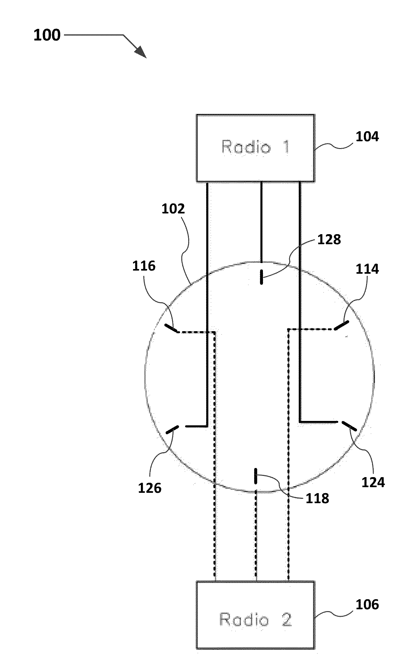
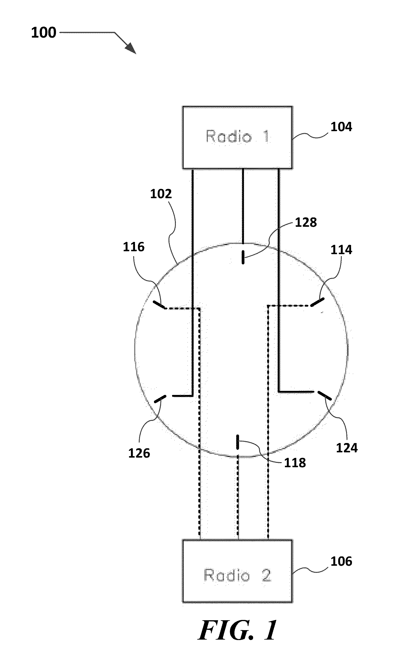
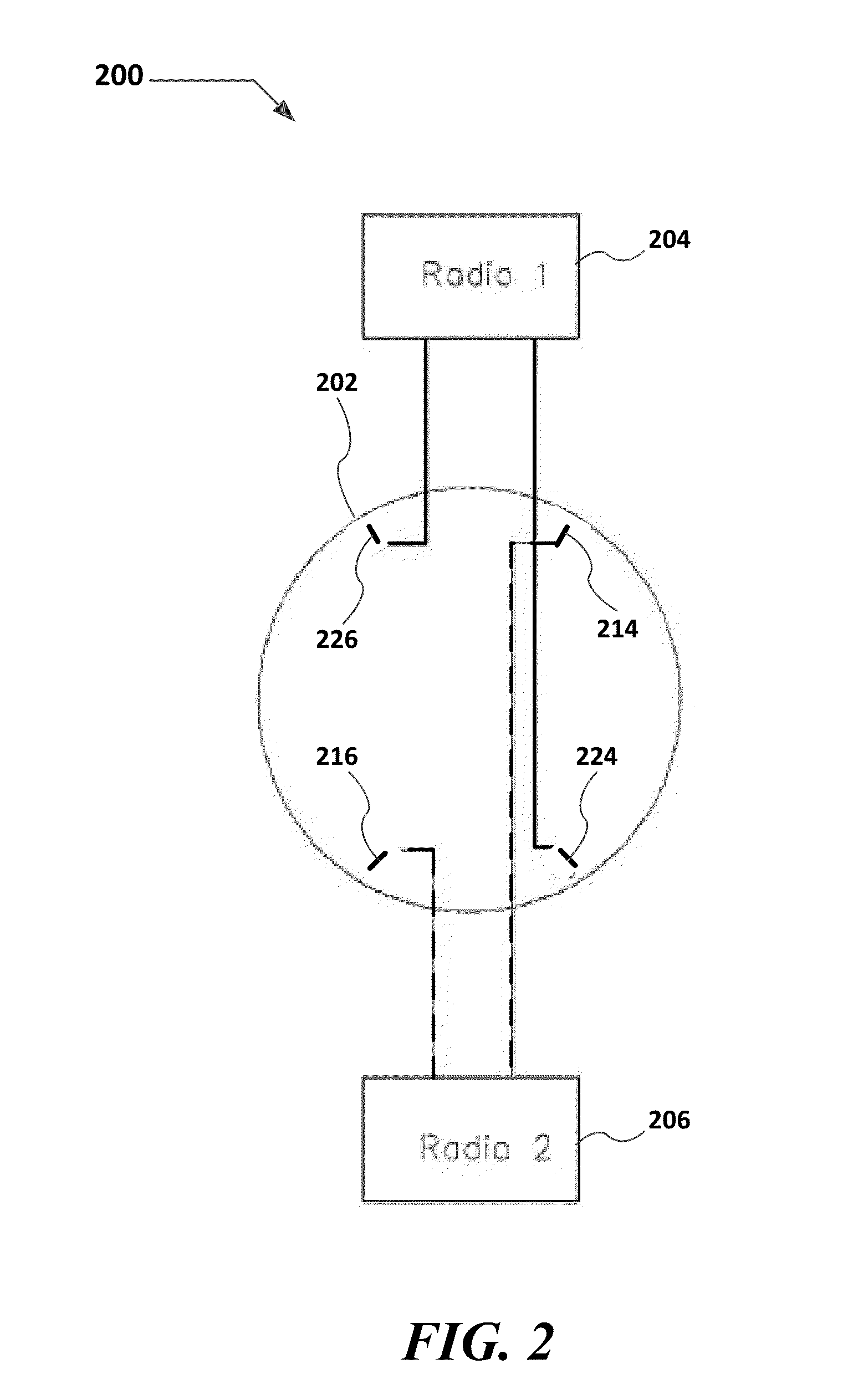
[0036]In general, a distributed omni-dual-band antenna system for use in a Wi-Fi access point is described. The distributed omni-dual-band antenna system includes an antenna array that may include 4, 6, or 8 antennas arranged in a circular array fashion along the Wi-Fi access point. Each antenna may be associated with a different Wi-Fi radio. The antennas for the different radios are interleaved (see FIGS. 1 and 2) in order to provide omni-coverage with minimal distortion. Each antenna element in the array may be dual-band one may also be semi-directional.

[0037]FIGS. 1 and 2 show schematic views of a two radio archite...


PUM


Abstract

A distributed broadband, omni-dual-band monopole antenna system for use in a Wi-Fi access point. The distributed omni-dual-band antenna system may include an antenna array that includes 4, 6, or 8 monopole antennas arranged in a circular array fashion along the perimeter of the access point. Each monopole antenna may be associated with a single Wi-Fi radio of the access point, and each of the antennas for the different radios are interleaved in order to provide omni-coverage with minimal distortion; that is, each antenna of the access point is alternated with antennas for different radios. A broadband printed omni-dual-band monopole antenna comprising three horizontal radiating elements arranged in an S-shape and a single vertical radiating element connected to the bottom-most horizontal radiating element is also disclosed.

Description

CROSS-REFERENCE TO RELATED APPLICATION[0001]This application claims priority of United States (“U.S.”) Provisional Patent Application Ser. No. 62 / 020,856, entitled “Distributed Omni-Dual Band Antenna System for a Wi-Fi Access Point,” filed on Jul. 3, 2014, to inventor Abraham Hartenstein, the disclosure of which is incorporated by reference herein in its entirety.BACKGROUND OF THE INVENTION[0002]1. Field of the Invention[0003]The present invention relates generally to antenna systems utilized in Wi-Fi devices, and more particularly, to a distributed omni-dual-band antenna system for use in smaller Wi-Fi devices.[0004]2. Related Art[0005]The use of wireless communication devices for data networking is growing at a rapid pace. Data networks that use “Wi-Fi” (“Wireless Fidelity”) are relatively easy to install, convenient to use, and supported by the IEEE 802.11 standard. Wi-Fi data networks also provide performance that makes Wi-Fi a suitable alternative to a wired data network for ma...

Claims


Application Information

Patent Timeline
Patent Type & Authority Applications(United States)
IPC IPC(8): H01Q21/30H01Q9/04H01Q19/10H04W84/12H04W88/08
CPCH01Q21/30H01Q19/10H04W88/08H04W84/12H01Q9/0407H01Q1/2291H01Q9/42H01Q21/205
Inventor HARTENSTEIN, ABRAHAM
Owner CAMBIUM NETWORKS
Why Eureka
Try Eureka