Method for the diagnosis of the offset of the resolver of an electric machine

a technology of resolver and rotor, which is applied in the direction of motor/generator/converter stopper, dynamo-electric converter control, instruments, etc., can solve the problems of low torque to be provided and serious risks for people on the vehicle or around, and achieve the effect of avoiding the drawbacks of the known technology

Active Publication Date: 2016-02-11
FAB ITAL MAGNETI MARELLI SPA
View PDF6 Cites 4 Cited by
  • Summary
  • Abstract
  • Description
  • Claims
  • Application Information

AI Technical Summary

Benefits of technology

[0016]The aim of the present invention is thus to provide a satisfactory solution to the aforementioned problems, while avoiding the drawbacks of the known technology. In particular, the aim of the present invention is to provide a method that may be implemented on board an electric motor for recognizing a modification of the offset of the resolver, for example a modification of the offset of the resolver caused accidentally, i.e. for recognizing if the actual offset of the resolver corresponds to the predetermined offset of the resolver.

Problems solved by technology

If the control unit of the motor does not recognize a modification of the offset of the resolver, the latter is no longer capable of determining the correct angular position of the motor or the position of minimum reluctance of the motor, which causes a lower torque to be provided or creates even serious drawbacks, such as unexpected behaviours in acceleration and deceleration when the vehicle is being driven, and—as a result of the erroneous control of the motor—the rupture of the rotor which determines the blocking of the motor drive shaft or the rupture of the pinion.
Equally disadvantageously, in the case of use of the electric motor in the start phase for the drive, the erroneous interpretation of the position of the rotor by the control unit may cause the inversion of the sign of the torque applied to the drive shaft with respect to that requested, causing the movement of the vehicle in the opposite direction to that desired, with consequent serious risks for the people on board the vehicle or around it.

Method used


Image

  • Method for the diagnosis of the offset of the resolver of an electric machine
  • Method for the diagnosis of the offset of the resolver of an electric machine
  • Method for the diagnosis of the offset of the resolver of an electric machine

Examples


Embodiment Construction

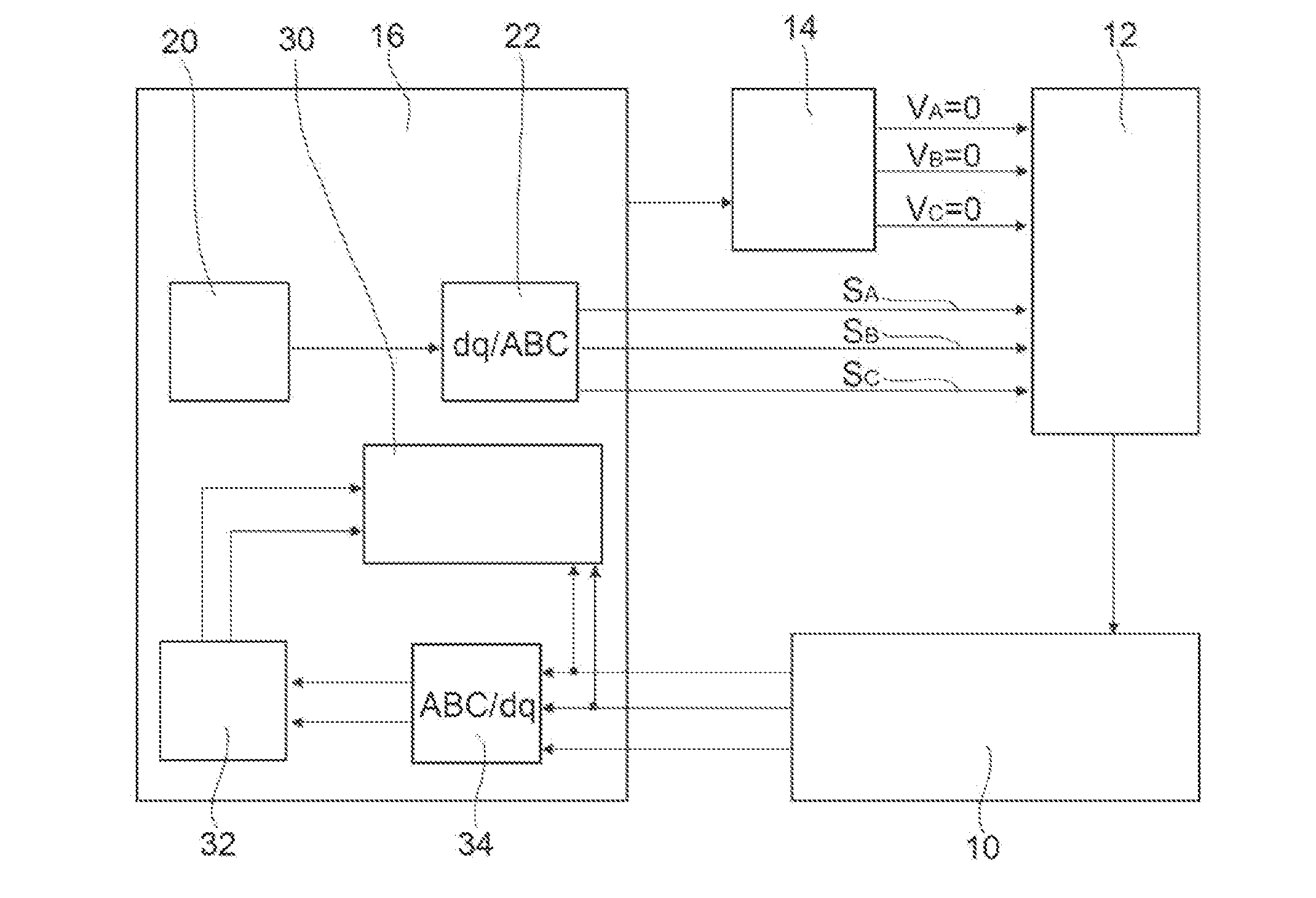
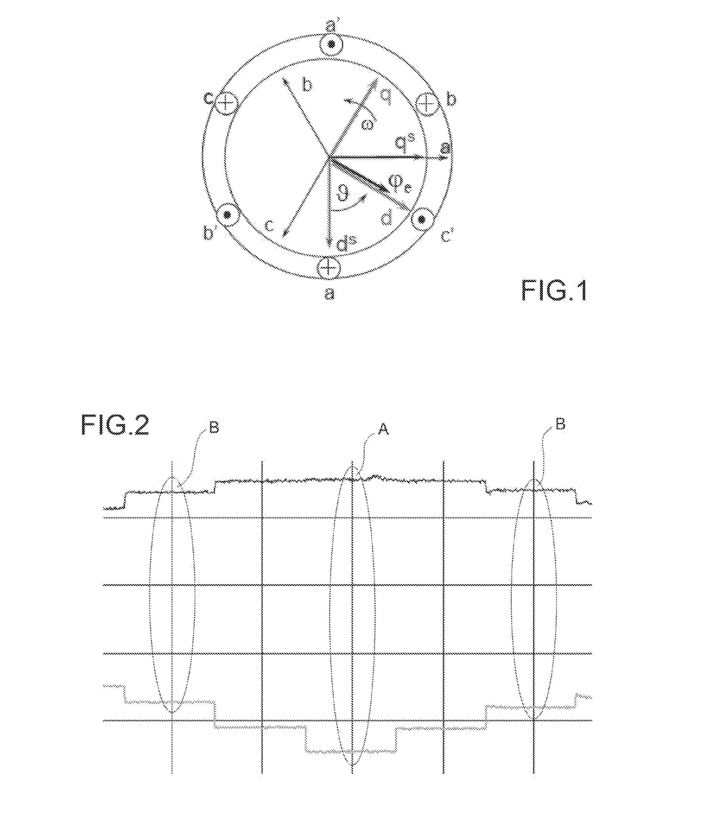
[0027]For a correct understanding of the method subject of the invention, in the following by way of introduction, the mathematical theory is presented of direct and inverse transformation of the reference system (“Park transforms”), from a three-phase reference system (phases A, B, C of an electric motor) to a rotating two-phase reference system (d-q), which rotates aligned to the rotor of an electric motor, and vice versa.

[0028]In FIG. 1 the rotational speed of the rotor is indicated by w, the axis d is the axis of minimum reluctance and the axis q is in phase quadrature with respect to the axis d.

[0029]Considering a transformation of the currents (but the same transforms are also applicable to the voltages), the reference system ABC is first of all convertible into a stationary reference system d-q (shown in the figure with apex s) in which the axes are located in a fixed reference, via the conversion matrix

iqsids=10-13-23iaib

(where the current ic=−ia−ib)

[0030]From a stationary t...


PUM


Abstract

A method for the diagnosis of the offset of the resolver of an electric motor, comprising acquiring a predetermined offset of a resolver associated with the electric motor; in a first transient, supplying an excitation current to the phases of the electric motor. As a consequence of the excitation current, a current established on the axis d of minimum reluctance and a current established on an axis q in phase quadrature with respect to the axis of minimum reluctance are determined. The correctness of the offset of the resolver is diagnosed if the current established on the axis d in the first transient is higher than the current established on the axis d in the second or third transient, and if the current established on the axis q in the first transient is lower than the current established on the axis q in the second or third transient.

Description

CROSS-REFERENCE TO RELATED APPLICATIONS[0001]The present application claims priority to and all the benefits of Italian Patent Application No. TO2014A000654, filed on Aug. 11, 2014, which is hereby expressly incorporated herein by reference in its entirety.BACKGROUND OF THE INVENTION[0002]1. Field of the Invention[0003]The present invention relates in general to electric motors and, in particular, to a diagnostic methodology for the recognition of the mutual positioning of a rotor and a stator in an electric motor, specifically an electric motor without brushes (brushless) with internal magnets, such as for example a drive motor for a vehicle.[0004]2. Description of the Related Art[0005]An electric motor, such as an electric starter motor or a drive motor for an electric or hybrid vehicle, is conventionally equipped with a device for sensing the angular position or resolver, adapted to determine the mutual angular position between a rotary shaft and a stationary portion of the motor...

Claims


Application Information

Patent Timeline
Patent Type & Authority Applications(United States)
IPC IPC(8): H02K11/00
CPCH02K11/0031B60L3/0038B60L3/0061B60L3/12B60L15/025B60L2220/14B60L2220/16B60L2240/421B60L2240/427B60L2240/429G01D5/2073G01D5/2448H02P6/183H02P21/32H02P2203/11Y02T10/64H02K11/225
Inventor STEFANI, ANDREAFOSSI, ALESSANDROBETRO', ROBERTORAIMONDI, MARCOCATERINI, CANIO
Owner FAB ITAL MAGNETI MARELLI SPA
Why Eureka
Try Eureka