Monitoring a multiplexed laser array in an optical communication system

a laser array and optical communication technology, applied in the field of monitoring lasers in optical communication systems, can solve the problems of inability to couple photodetectors to each of the lasers, and the wavelength of light may not be accurately monitored by photodetectors directly coupled to the multiplexed lasers

Active Publication Date: 2016-02-11
APPLIED OPTOELECTRONICS
View PDF0 Cites 24 Cited by
  • Summary
  • Abstract
  • Description
  • Claims
  • Application Information

AI Technical Summary

Problems solved by technology

In multiplexed laser arrays, however, it may not be feasible to couple a photodetector to each of the lasers, for example, within the limited space of a multi-channel...

Method used


Image

  • Monitoring a multiplexed laser array in an optical communication system
  • Monitoring a multiplexed laser array in an optical communication system
  • Monitoring a multiplexed laser array in an optical communication system

Examples


Embodiment Construction

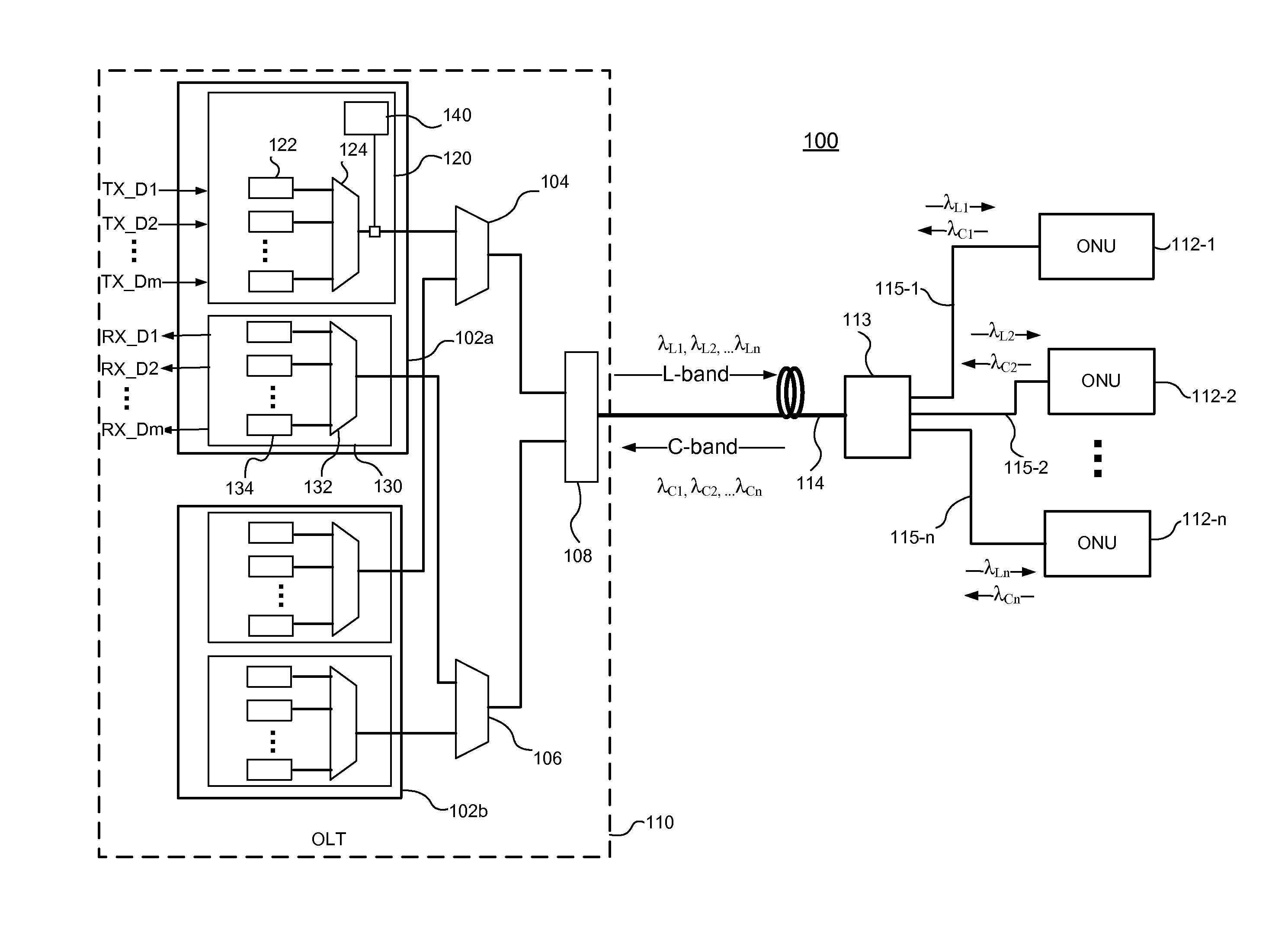
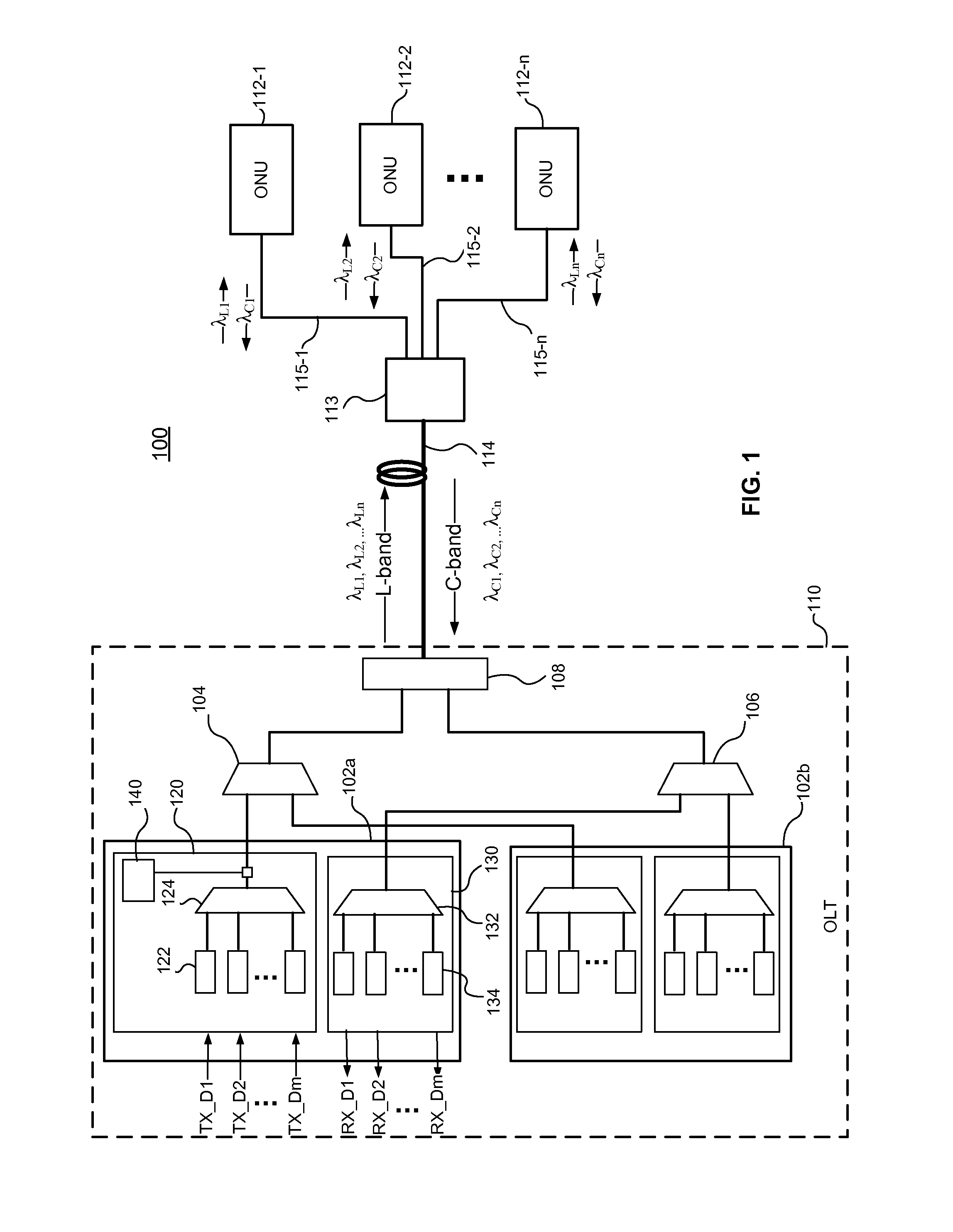
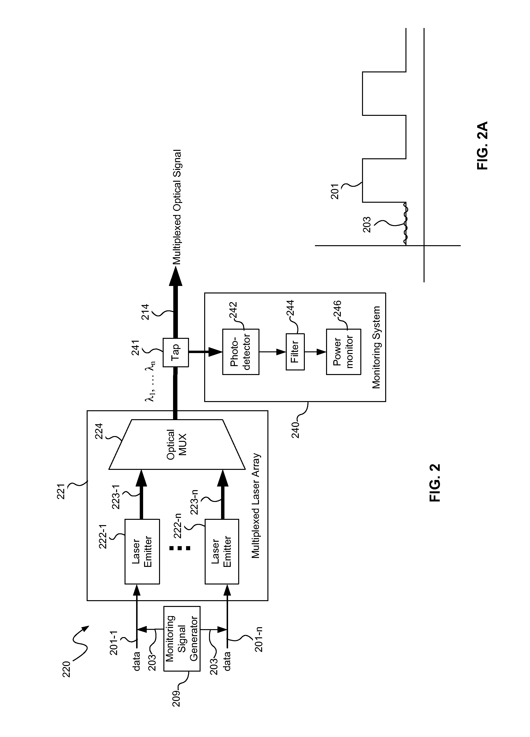
[0014]Individual channels of a multiplexed laser array in a multi-channel optical transmitter are monitored, consistent with embodiments of the present disclosure, at an output of an optical multiplexer. The monitoring may be used to confirm proper operation of each of the channels in the multiplexed laser array and / or to perform wavelength locking on each of the channels. Monitoring at the output of the optical multiplexer avoids the use of multiple photodetectors coupled directly to multiple lasers in the multiplexed laser array. The multiplexed laser array generally includes a plurality of laser emitters optically coupled to an optical multiplexer such as an arrayed waveguide grating (AWG). An optical transmitter with a monitored multiplexed laser array may be used, for example, in an optical line terminal (OLT) in a wavelength division multiplexed (WDM) passive optical network (PON) or in any other type of WDM optical communication system capable of transmitting optical signals ...


PUM


Abstract

Individual channels of a multiplexed laser array in a multi-channel optical transmitter are monitored at an output of an optical multiplexer. The monitoring may be used to confirm proper operation of each of the channels in the multiplexed laser array and/or to perform wavelength locking on each of the channels. Monitoring at the output of the optical multiplexer avoids the use of multiple photodetectors coupled directly to multiple lasers in the multiplexed laser array. The multiplexed laser array generally includes a plurality of laser emitters optically coupled to an optical multiplexer such as an arrayed waveguide grating (AWG). An optical transmitter with a monitored multiplexed laser array may be used, for example, in an optical line terminal (OLT) in a wavelength division multiplexed (WDM) passive optical network (PON) or in any other type of WDM optical communication system capable of transmitting optical signals on multiple channel wavelengths.

Description

TECHNICAL FIELD[0001]The present invention relates to monitoring lasers in optical communication systems and more particularly, to monitoring individual channels in a multiplexed laser array at an output of an optical multiplexer.BACKGROUND INFORMATION[0002]Fiber optic communications networks may increase the amount of information carried on an optical fiber by multiplexing different optical signals on different wavelengths using wavelength division multiplexing (WDM). In a WDM passive optical network (PON), for example, a trunk fiber carries optical signals at multiple channel wavelengths to and from an optical branching point and the branching point provides a simple routing function by directing signals of different wavelengths to and from individual subscribers. In this case, each subscriber may be assigned one or more of the channel wavelengths on which to send and / or receive data.[0003]To transmit and receive optical signals over multiple channel wavelengths, an optical line t...

Claims


Application Information

Patent Timeline
IPC IPC(8): H04B10/079H01S5/0683H01S5/40H04B10/40H04B10/50H04J14/02
CPCH04B10/07955H01S5/4025H04B10/503H04J14/02H04B10/40H01S5/0683H01S5/0268H01S5/0687H01S5/4087H04J14/0282H04B10/506H04B10/572
Inventor ZHENG, JUNWANG, YIHO, I-LUNGANSELM, KLAUS ALEXANDERZHANG, HUANLIN
Owner APPLIED OPTOELECTRONICS
Why Eureka
Try Eureka