Device For Carrying Out A Transapical Mitral Valve Annuloplasty

a technology of mitral valve and device, which is applied in the field of devices for carrying out transapical mitral valve annuloplasty, can solve the problems of difficult to secure the prosthetic implant, laborious to locate the mitral annulus, and relatively large investment of tim

Active Publication Date: 2016-02-18
VOLA MARCO +1
View PDF5 Cites 6 Cited by
  • Summary
  • Abstract
  • Description
  • Claims
  • Application Information

AI Technical Summary

Benefits of technology

This patent aims to solve problems in heart surgery by improving the placement of sutures and the fixing of an implant in a minimally invasive way without the need for extracorporeal circulation. It also aims to reduce the risk of blood leakage and improve the precision of implant placement and tissue fixation. Another objective is to provide a sealed device at the body to enable the passage of movement control members and prevent blood from leaking. Additionally, the patent seeks to address the issue of reducing the tightening of the valve annulus to avoid any leak risk after installing and securing the braid forming a prosthetic implant relative to the mitral annulus.

Problems solved by technology

However, these solutions make laborious to locate the mitral annulus.
This results in a relatively large investment of time.
Difficulties may also arise for the securing of the prosthetic implant at the native mitral annulus.

Method used


Image

  • Device For Carrying Out A Transapical Mitral Valve Annuloplasty
  • Device For Carrying Out A Transapical Mitral Valve Annuloplasty
  • Device For Carrying Out A Transapical Mitral Valve Annuloplasty

Examples


Embodiment Construction

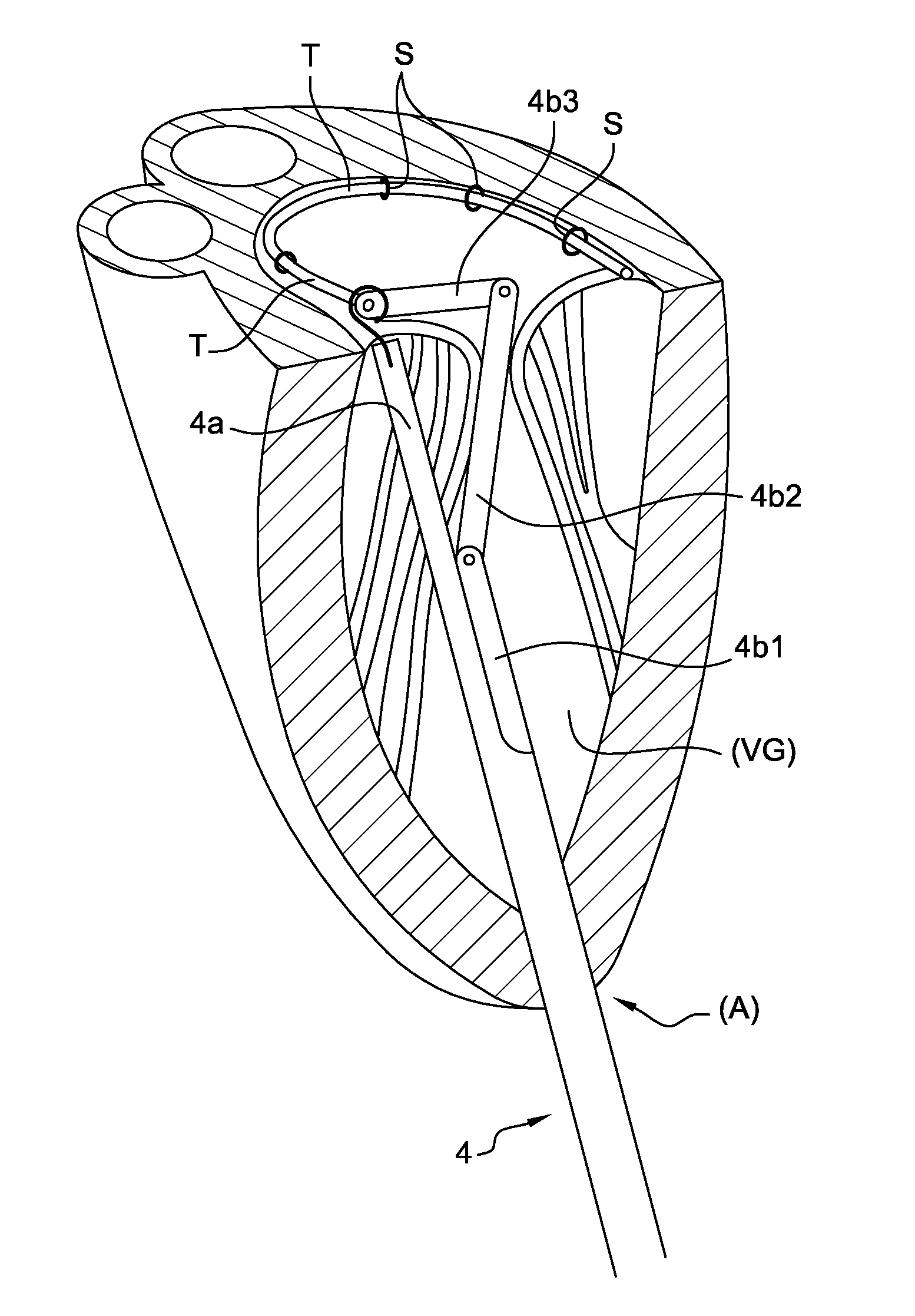
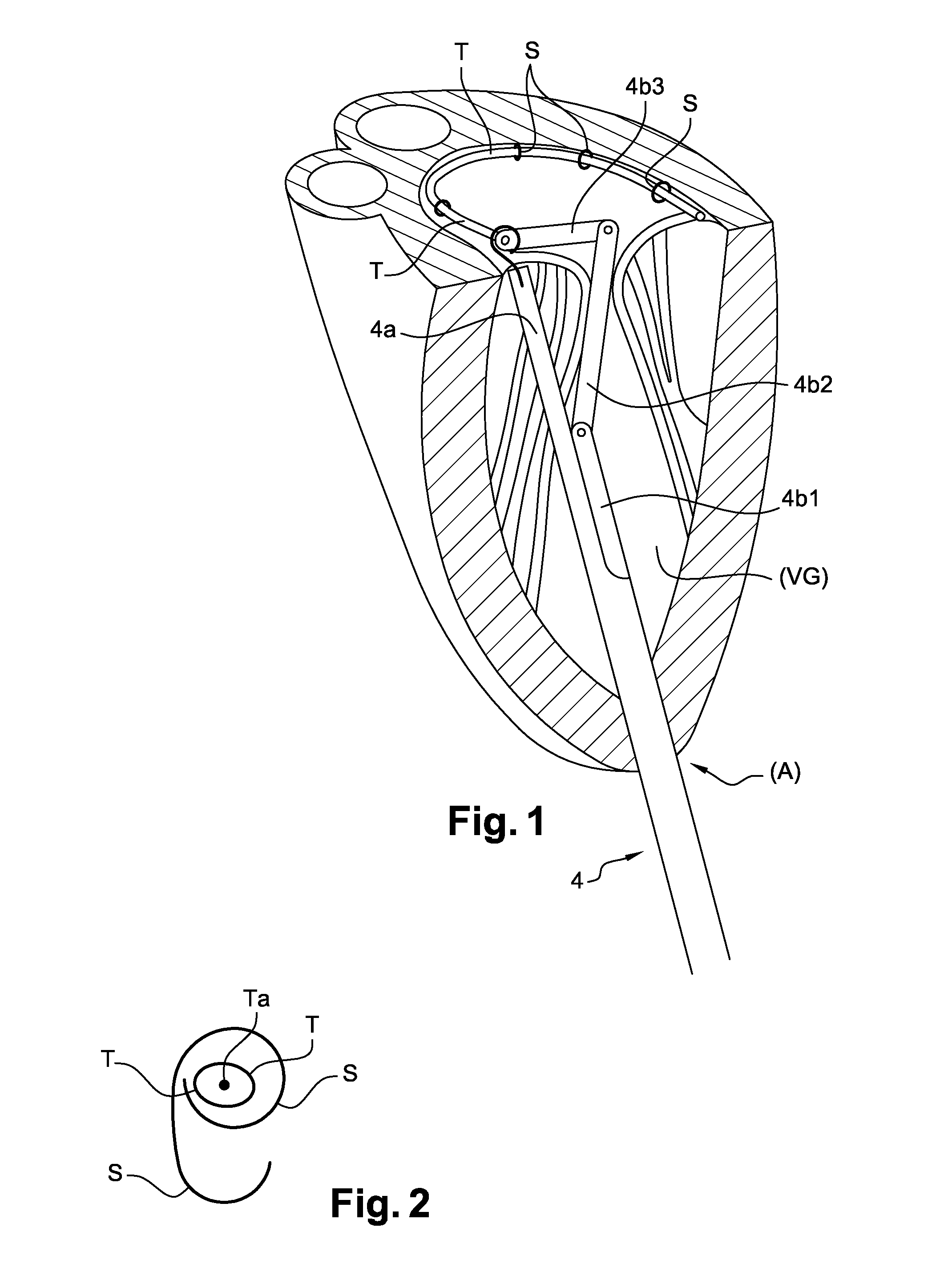
[0047]The device is intended to be positioned in a sealed introducer of any known and suitable type (not shown) disposed in the thoracic cavity between two ribs to get into the left ventricle (LV) through the apex (A) of the heart (FIG. 1).

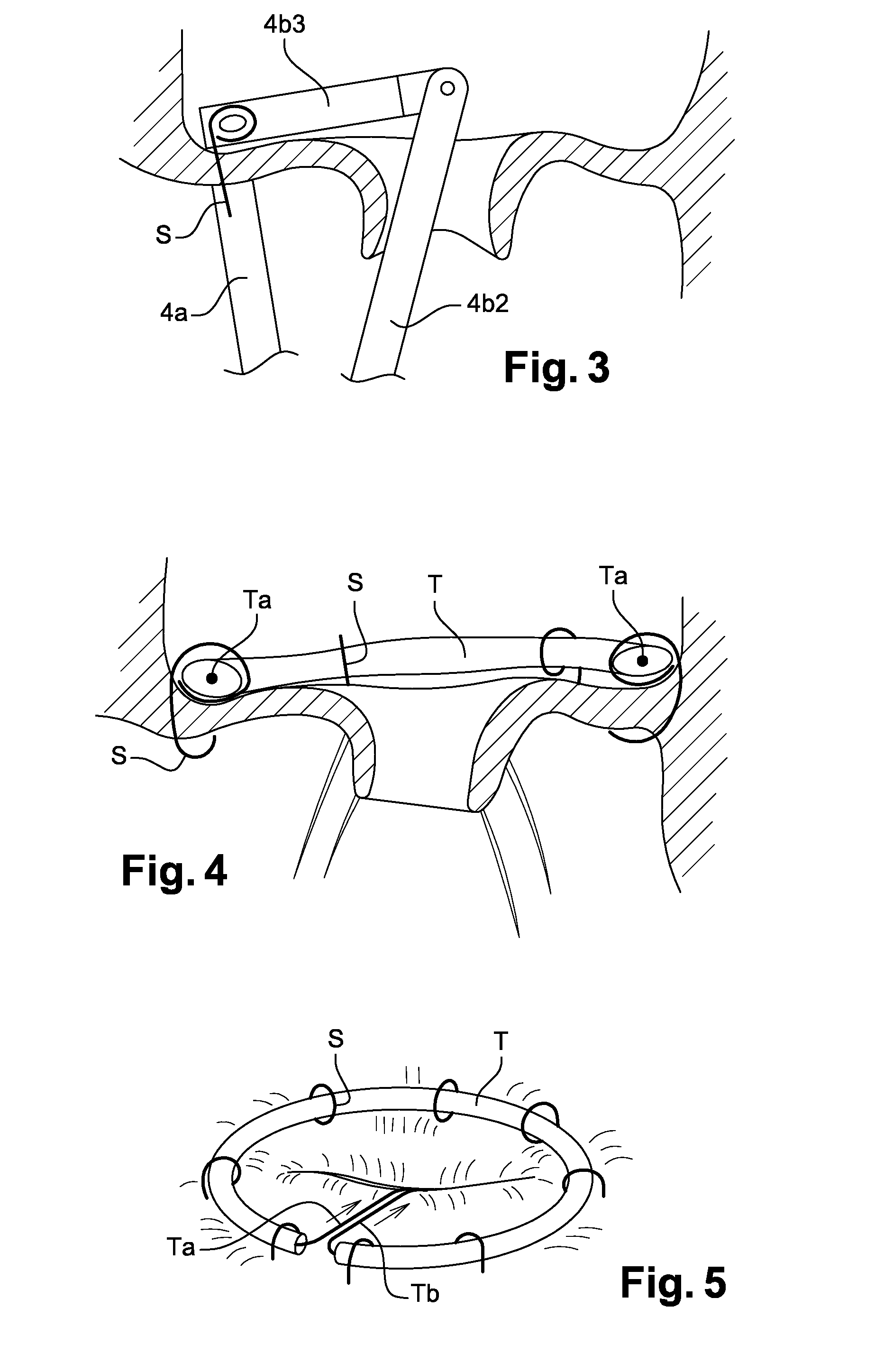
[0048]The device comprises a body (1) having a handle (2) and at least one control member (3), e.g. in the form of a trigger, to act on a assembly for the installing and securing a prosthetic implant as a braid (T) at the mitral annulus by means of suture elements (S).

[0049]The assembly consists of a tubular arm (4) comprising two portions (4a) and (4b) adapted to be spaced upon introduction into the left ventricle (LV). One of the portions (4a) receives the sutures (S) and is intended to be placed in contact in the commissure between the mitral valve and the walls of the left ventricle. The other portion (4b) receives the braid (T) and is shaped to be introduced through the mitral valve to be positioned at right angles to the end of the portion (...


PUM


Abstract

The device is intended to be positioned in a sealed introducer arranged in the thoracic cavity between two ribs in order to penetrate into the left ventricle, passing through the apex of the heart. According to the invention, the device includes a body having a handle and at least one control member capable of acting on an assembly for installing and securing a braid to the mitral annulus by means of suturing elements, the assembly has a mechanism capable of enabling the extraction of a suture through the mitral valve while also being capable of enclosing the braid and becoming anchored to the periphery of the mitral annulus under the clamping effect of the suture, exerting two opposing pressure-bearing forces.

Description

FIELD OF THE INVENTION[0001]The invention relates to a device for carrying out a transapical mitral valve annuloplasty.BACKGROUND OF THE INVENTION[0002]In other words, the annuloplasty aims to reduce the size of the mitral annulus by shortening the attach of the small valve by means of a kinking, the fulcrum being caught between the commissures. Commissure means a narrowing of the posterior portion perimeter of the mitral annulus by performing thereon kinking with stitches, resulting in a decrease in the antero-posterior and latero-lateral diameter of the mitral valve.[0003]A mitral annuloplasty is performed as correcting means of wich mitral leak mechanism is a dilatation of the mitral annulus (with loss of coaptation of the valvular banks) or, in addition to correcting the leak with another mechanism, (mitral valve prolapse) to increase the coaptation of the posterior mitral valve relative to the anterior mitral valve.[0004]A mitral annuloplasty is a long and tough operation which...

Claims


Application Information

Patent Timeline
IPC IPC(8): A61F2/24A61B17/04
CPCA61F2/2466A61B17/0469A61B2017/0498A61B17/0482A61F2/2445A61B17/068A61B2017/0488A61B2017/0649
Inventor VOLA, MARCOPAIN, BERNARD
Owner VOLA MARCO
Why Eureka
Try Eureka