
Ozone generator

a generator and ozone technology, applied in the field of ozone generators, can solve the problems of limited reduction of switching loss and noise, and possibly inability to supply a sufficient amount of energy,

Inactive Publication Date: 2016-02-18
NGK INSULATORS LTD
View PDF5 Cites 7 Cited by
  • Summary
  • Abstract
  • Description
  • Claims
  • Application Information

AI Technical Summary

Benefits of technology

The patent describes a way to use ozone in a vehicle to help ignite the fuel. It also discusses a circuit that generates pulses to reduce switching loss and noise. The technical effect of this patent is to improve the efficiency and reliability of ozone generation for use in vehicles and to improve the performance of pulse generating circuits.

Problems solved by technology

Therefore, there is a limitation in reducing a switching loss and noise.
The pulse generating circuit disclosed in Japanese Laid-Open Patent Publication No 2014-036502 may possibly be unable to supply a sufficient amount of energy for producing electric discharges because a pulse voltage is generated only during the ON period of the semiconductor switch.

Method used


Image

  • Ozone generator
  • Ozone generator
  • Ozone generator

Examples


Embodiment Construction

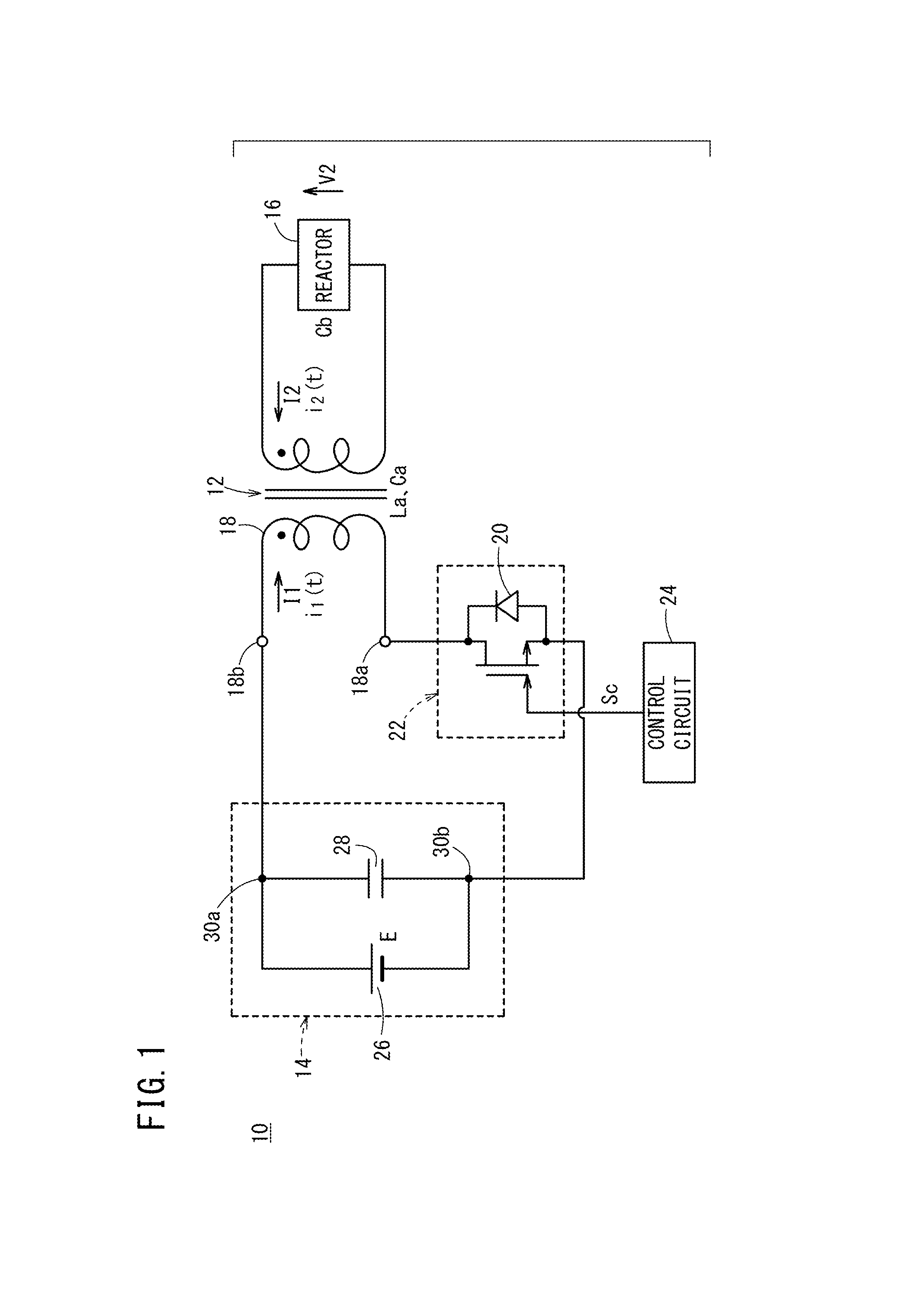
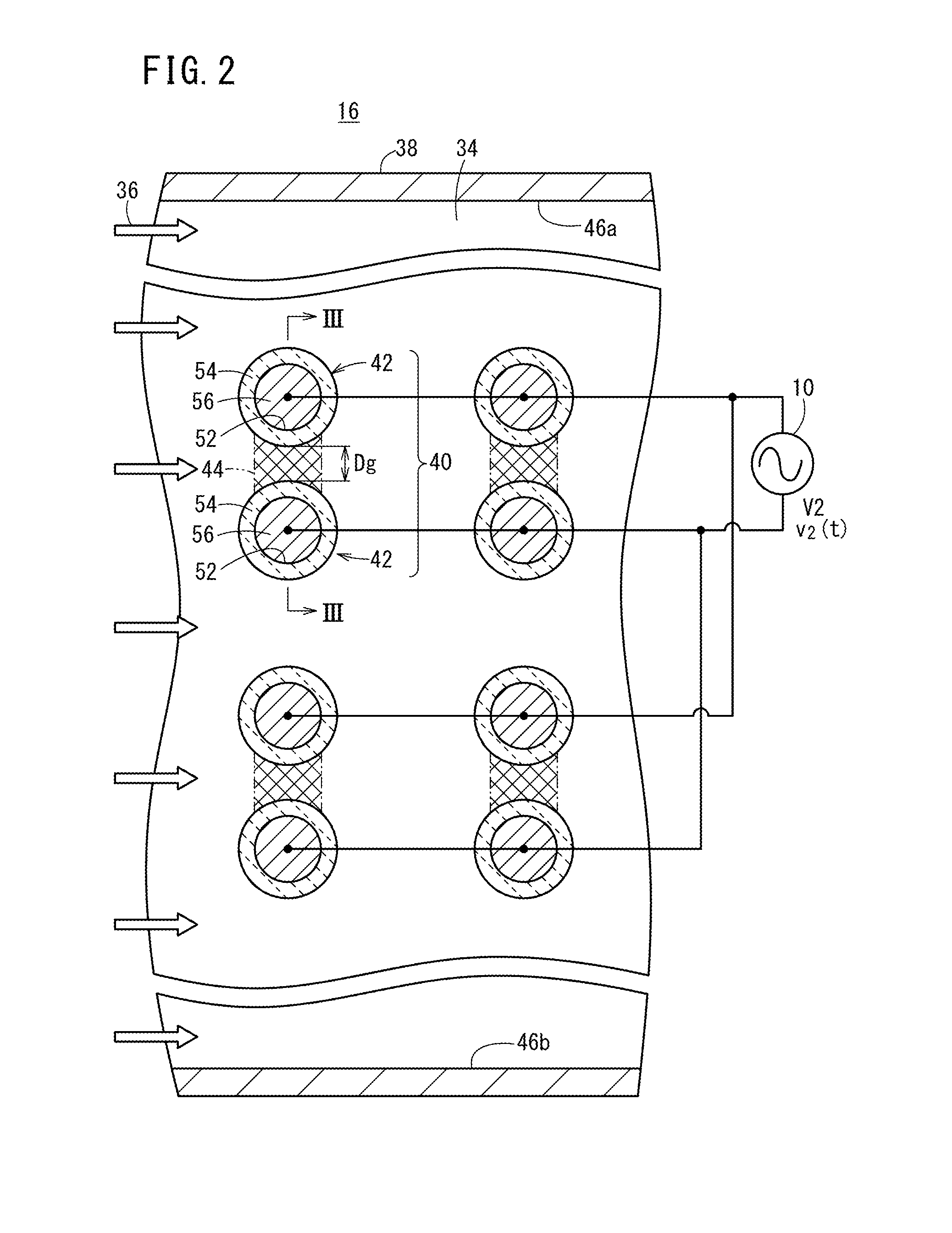
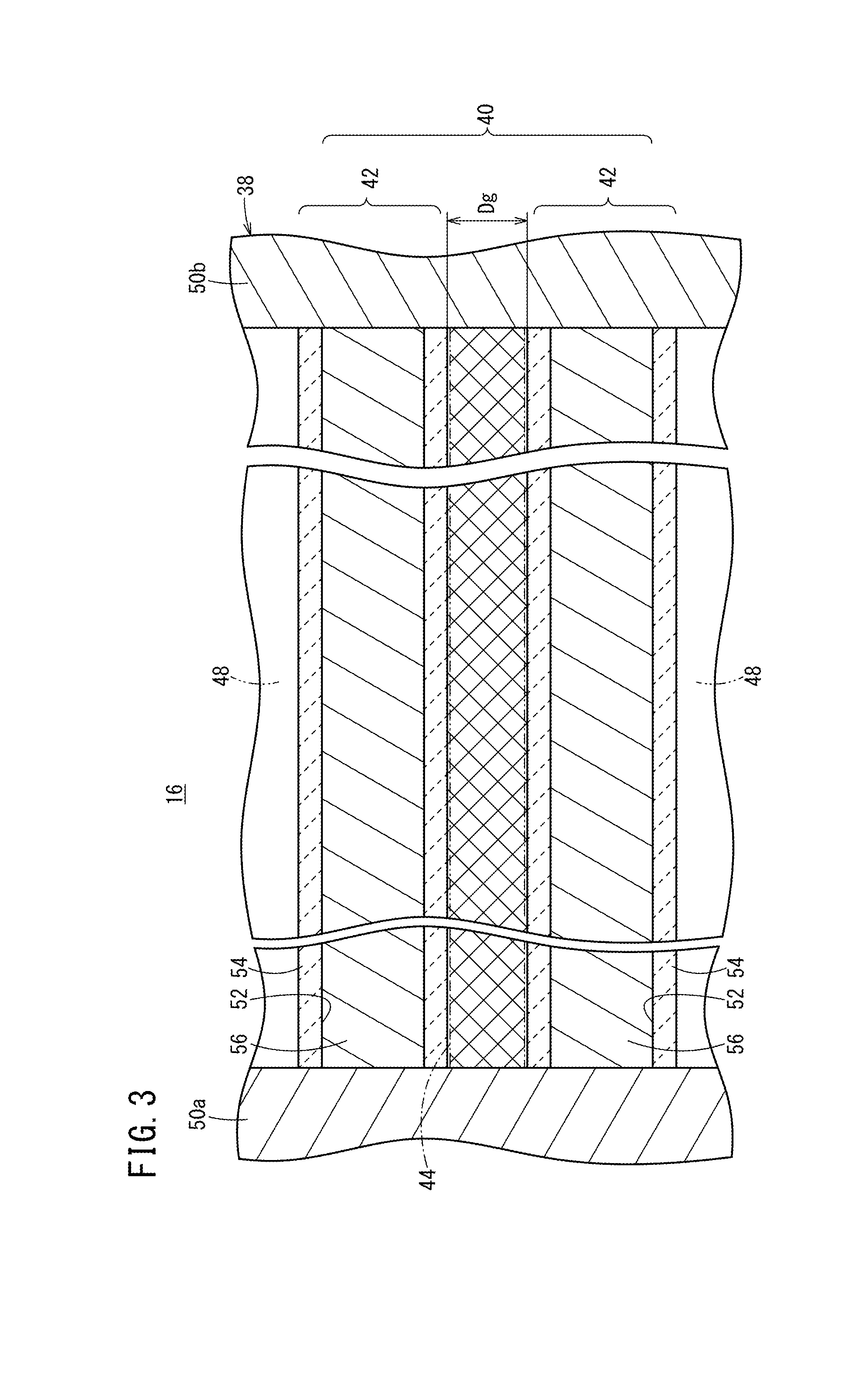
[0038]An ozone generator according to an embodiment of the present invention will be described below with reference to FIGS. 1 through 5.

[0039]As shown in FIG. 1, an ozone generator 10 according to an embodiment of the present invention includes a transformer 12, a direct current (DC) power supply unit 14 connected to the primary side of the transformer 12, a reactor 16 connected to the secondary side of the transformer 12, a semiconductor switch (switching unit) 22 connected between one end 18a of a primary winding 18 of the transformer 12 and the direct current power supply unit 14, and having a diode 20 connected in reverse-parallel, and a control circuit 24 for applying voltage to the reactor 16 by implementing ON-OFF control of the semiconductor switch 22.

[0040]The direct current power supply unit 14 is formed by connecting a direct current power supply 26 and a capacitor 28 in parallel. Therefore, a positive electrode terminal 30a of the direct current power supply unit 14 (no...


PUM

PropertyMeasurementUnit
pressureaaaaaaaaaa
switching frequencyaaaaaaaaaa
voltageaaaaaaaaaa

Abstract

An ozone generator includes a transformer, a direct current power supply unit connected to a primary side of the transformer, a reactor connected to a secondary side of the transformer, a semiconductor switch connected between one end of a primary winding of the transformer and the direct current power supply unit, and a control circuit for implementing ON-OFF control of the semiconductor switch at a set switching frequency to thereby apply a voltage to the reactor. The interior of the reactor is set to conditions for making it easy to generate an electric discharge therein.

Description

CROSS-REFERENCE TO RELATED APPLICATION[0001]This application is based upon and claims the benefit of priority from Japanese Patent Application No. 2014-165349 filed on Aug. 15, 2014, the contents of which are incorporated herein by reference.BACKGROUND OF THE INVENTION[0002]1. Field of the Invention[0003]The present invention relates to an ozone generator, and more particularly to an ozone generator which is suitable for in-vehicle applications, for example.[0004]2. Description of the Related Art[0005]Generally, the discharging circuits for ozone generators include, for example, a high-frequency power supply (RF power supply) disclosed in Japanese Laid-Open Patent Publication No. 11-233294, and discharging circuits disclosed in Japanese Patent No. 3811681, Japanese Patent No. 4418212, and Japanese Laid-Open Patent Publication No. 2014-036502.[0006]The high-frequency power supply disclosed in Japanese Laid-Open Patent Publication No 11-233294 has an oscillating circuit, a power ampli...

Claims


Application Information

Patent Timeline
Patent Type & Authority Applications(United States)
IPC IPC(8): C01B13/11
CPCC01B2201/90C01B13/11
Inventor TERAZAWA, TATSUYAYOKOI, SHOJITAKASE, NAOYA
Owner NGK INSULATORS LTD
Learn More