
Temperature sensor circuit

a technology of temperature sensor and circuit, which is applied in the direction of thermometers with a/d converters, instruments, heat measurement, etc., can solve the problems of poor temperature measurement accuracy and increase in temperature within die circuitry

Active Publication Date: 2016-02-18
NXP USA INC
View PDF10 Cites 20 Cited by
  • Summary
  • Abstract
  • Description
  • Claims
  • Application Information

AI Technical Summary

Benefits of technology

The present invention provides a temperature sensor circuit that can be used in electronic circuitry to monitor the temperature of a location within the circuitry. The temperature sensor circuit uses a difference between two voltages, one of which is proportional to temperature and the other of which is complementary to temperature, to measure the temperature. The circuit includes a reference circuit and temperature measuring circuitry, and can output a signal representing the sensed temperature based on the difference between the two voltages. The invention addresses the issue of non-linearity in DAC-based temperature sensors and provides a solution for accurate temperature measurement over a wide range of temperatures. The invention can be used in electronic circuitry to prevent overheating and damage to the electronic component caused by overheating.

Problems solved by technology

For example, it is important to manage the on-die temperature in a multi-core SOC (“system on chip”) due to issues pertaining to the positive feedback mechanism associated with leakage current and temperature, in that leakage current results in increases in temperature within the die circuitry.
This approach, however, has suffered from DAC code-to-temperature non-linearity issues; that is, such temperature sensors cannot achieve good linearity over a wide temperature range, resulting in poor temperature measurement accuracy.

Method used


Image

  • Temperature sensor circuit
  • Temperature sensor circuit
  • Temperature sensor circuit

Examples


Embodiment Construction

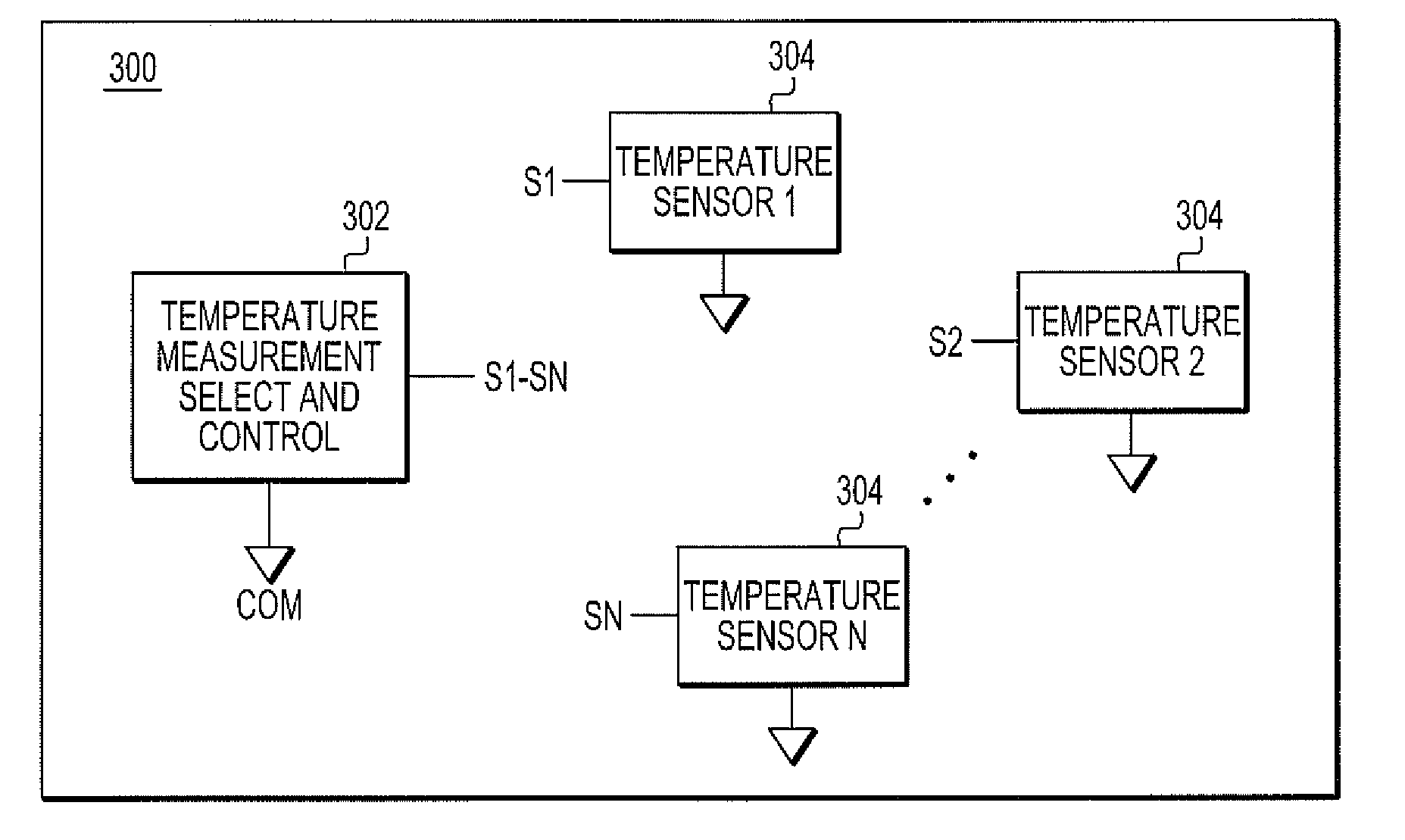
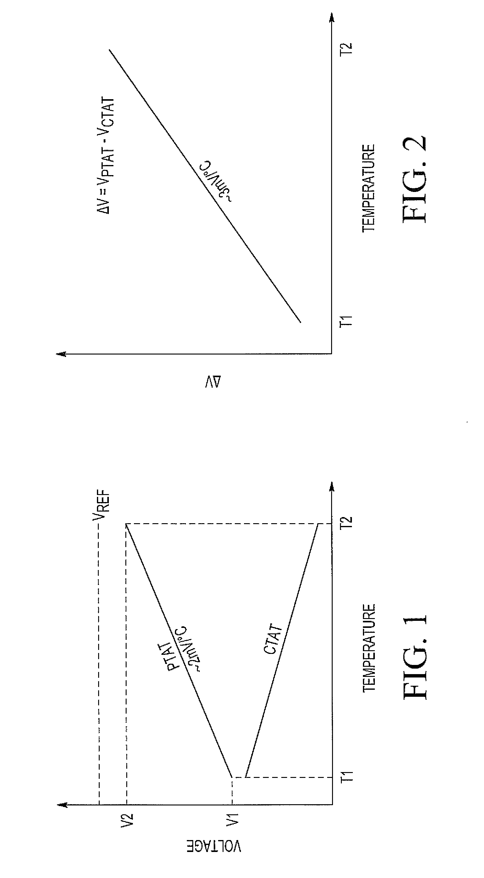
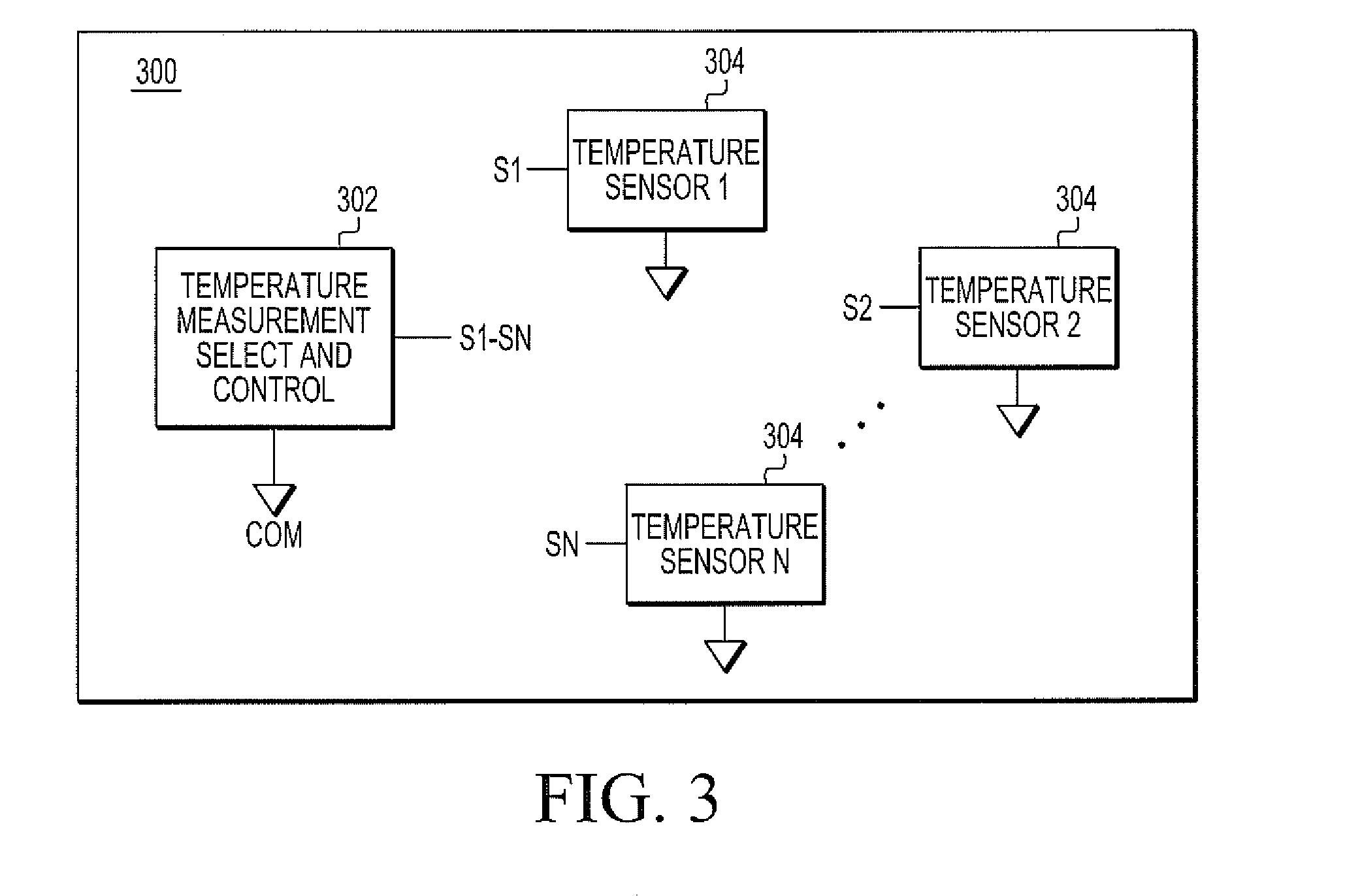
[0012]Aspects of the present invention essentially provide a temperature sensing circuit or process implemented on electronic circuitry that senses the temperature at a location (site) within the electronic circuitry, and then outputs a signal representing such a sensed temperature based on a difference between PTAT and CTAT voltages produced as a function of the sensed temperature.

[0013]FIG. 1 illustrates an exemplary plot showing the relationships of PTAT and CTAT voltages to temperatures (e.g., operating temperatures of electronic circuitry (e.g., in an integrated circuit) in which a temperature sensor circuit configured in accordance with embodiments of the present invention would be implemented). As will be further disclosed herein, circuitry within the temperature sensor circuit outputs a voltage (for a fixed current) that increases in proportion to a temperature rise or has a positive temperature coefficient, within a portion of the overall electronic circuitry in which a tem...


PUM

PropertyMeasurementUnit
temperatureaaaaaaaaaa
operating temperatureaaaaaaaaaa
voltageaaaaaaaaaa

Abstract

A temperature sensor circuit implemented in electronic circuitry that senses the temperature at a site, digitizes the sensed temperature, and then outputs a signal representing such a sensed temperature. The temperature sensor circuit converts a voltage signal that is proportional to the temperature to a first digital value. The temperature sensor circuit converts a voltage signal that is inversely proportional to the temperature to a second digital value. The sensed temperature is determined as a function of a difference between the first and second digital values.

Description

CROSS-REFERENCE TO RELATED APPLICATION[0001]This application is related to U.S. Patent Application Ser. No. 14 / 258,629, which is hereby incorporated by reference herein.TECHNICAL FIELD[0002]The present invention is related in general to a temperature sensor circuit, and in particular, to a temperature sensor circuit implemented within electronic circuitry.BACKGROUND INFORMATION[0003]It has become increasingly important to monitor temperatures within electronic circuitry (e.g., on an integrated circuit (“IC”) die, or chip). For example, it is important to manage the on-die temperature in a multi-core SOC (“system on chip”) due to issues pertaining to the positive feedback mechanism associated with leakage current and temperature, in that leakage current results in increases in temperature within the die circuitry. A temperature sensor can be used to monitor the temperature of an electronic component, such as a CPU (“central processing unit”), GPU (“graphics processing unit”), MPU (“m...

Claims


Application Information

Patent Timeline
Patent Type & Authority Applications(United States)
IPC IPC(8): G01K7/01
CPCG01K7/01G01K2219/00
Inventor RAMARAJU, RAVINDRARAJBEARDEN, DAVID R.
Owner NXP USA INC
Learn More