
Multi-resolution depth estimation using modified census transform for advanced driver assistance systems

a driver assistance system and census transform technology, applied in image analysis, image enhancement, instruments, etc., can solve the problems of noisy depth maps acquired by depth sensors, poor depth boundary generation, fast and computationally simple methods, etc., and achieve the effect of improving the quality of estimated depth maps

Inactive Publication Date: 2016-02-18
ILLINOIS INSTITUTE OF TECHNOLOGY
View PDF6 Cites 30 Cited by
  • Summary
  • Abstract
  • Description
  • Claims
  • Application Information

AI Technical Summary

Benefits of technology

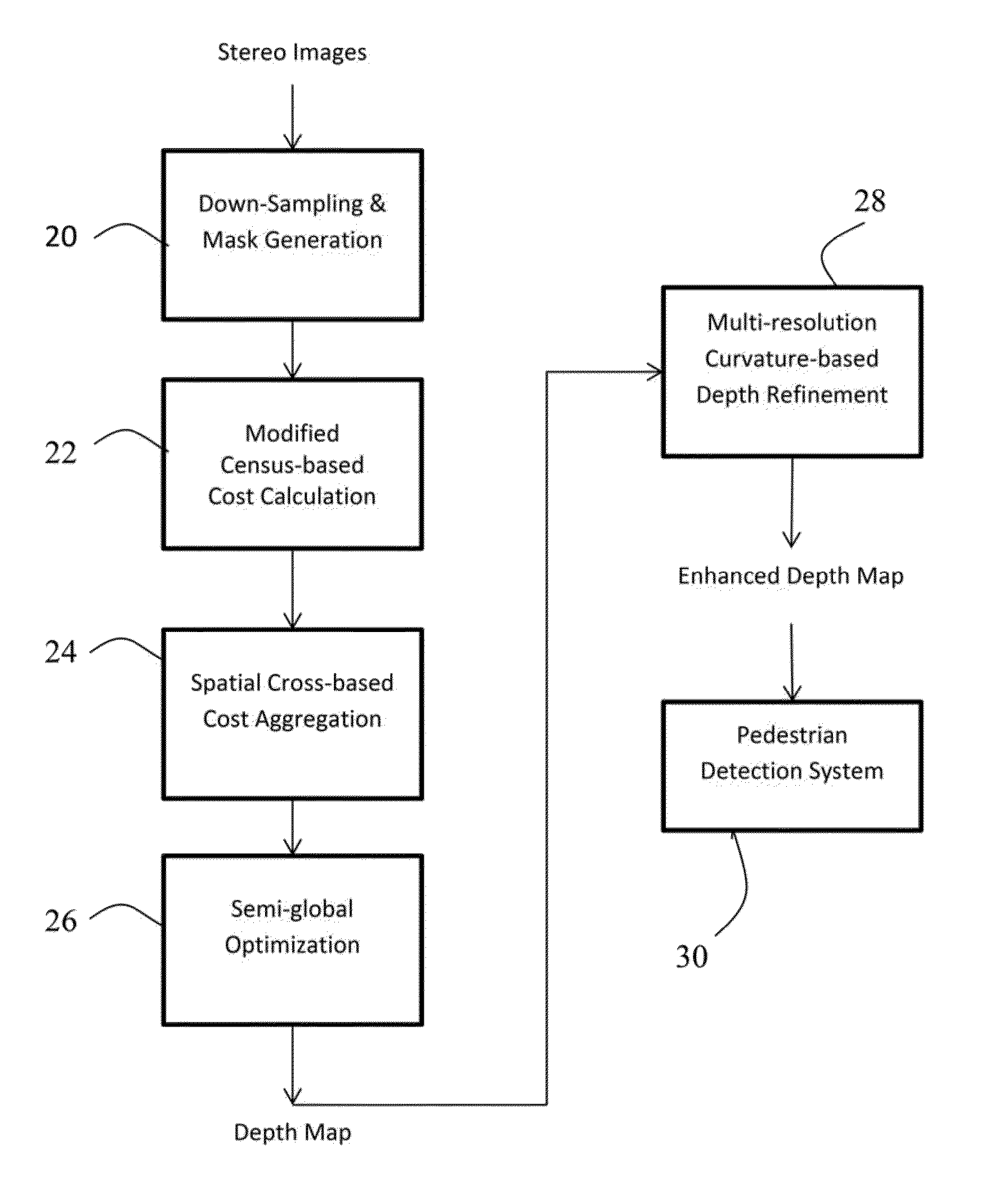
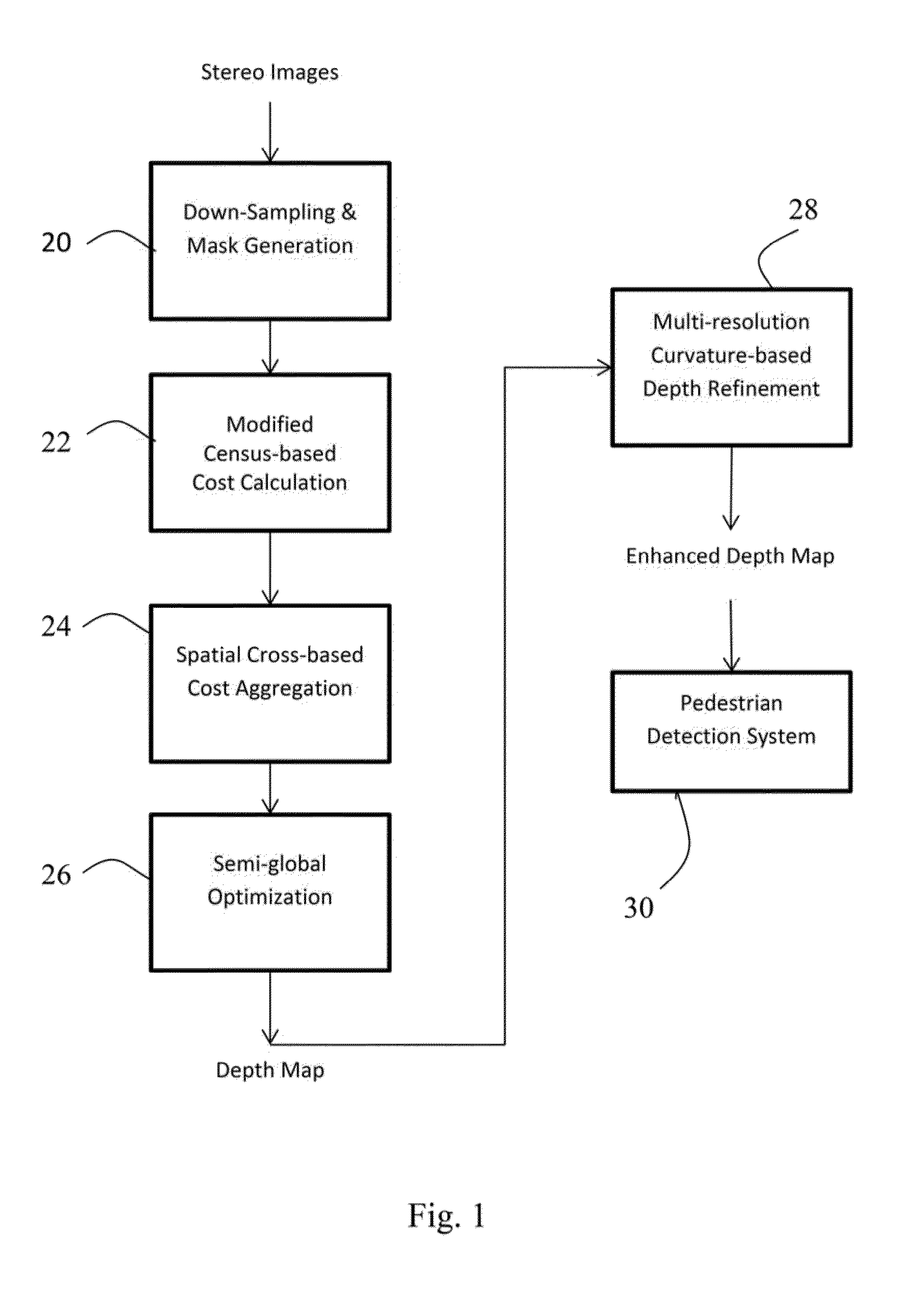
The invention provides an improved method for depth estimation based on non-parametric Census transform and semi-global optimization. The method improves the quality of estimated depth maps to fulfill the demands of real-time applications such as 3D scene reconstruction and / or stereo-based pedestrian detection. It includes a method of determining depth in images by reducing image resolution in stereo images, creating an image mask as a function of pixel curvatures, determining a computational cost value for a plurality of pixels, and matching pixels between stereo images and optimizing a value for the matching pixels to obtain an estimated depth map. Compared to existing hole filling techniques, the depth refinement algorithm uses a trilateral filter to enhance the quality of the estimated depth map by making the boundaries sharper and correcting misaligned regions. The method ensures that no new depth values are introduced during the up-sampling and adjusts the new depth values by mapping them to the nearest depth value which already exists in the depth map.

Problems solved by technology

Depth maps acquired by the depth sensors are usually noisy and suffer from poorly generated depth boundaries.
The local methods are fast and computationally simple but, they are highly error-prone and the estimated depth maps are usually inaccurate.
However, due to the computational complexity of such algorithms, it is not feasible to exploit them in real-time applications.
However, it achieves limited performance under illumination changes.
Despite the advantages of different depth estimation techniques, there are several problems in the generated depth maps.
The existence of holes and sensitivity to noise and illumination changes are the main significant problems.

Method used


Image

  • Multi-resolution depth estimation using modified census transform for advanced driver assistance systems
  • Multi-resolution depth estimation using modified census transform for advanced driver assistance systems
  • Multi-resolution depth estimation using modified census transform for advanced driver assistance systems

Examples


examples

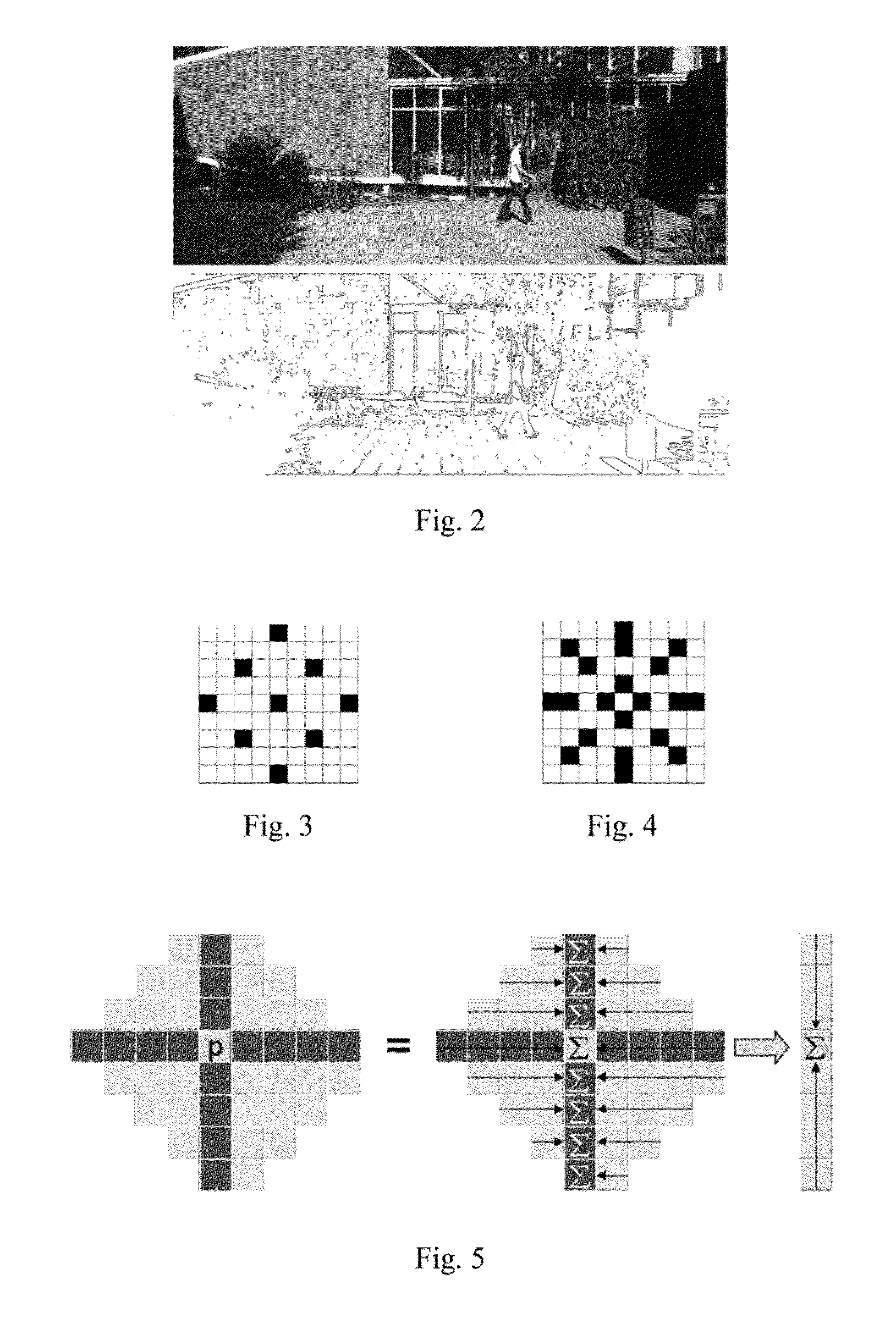
[0054]Simulations were performed to show the efficiency of the method compared with those of the state-of-the-art SGM-based stereo matching methods. The performance of the depth estimation and refinement algorithms of this invention were evaluated against the Middlebury data (D. Scharstein et al. “High-accuracy stereo depth maps using structured light,”Proc of IEEE Conf on Computer Vision and Pattern Recognition (CVPR), vol. 1, pp. 195-202, June 2003), and the KITTI stereovision benchmark suite (A. Geiger et al., “Are we ready for Autonomous Driving? The KITTI Vision Benchmark Suite,”Proc. of IEEE Conf on Computer Vision and Pattern Recognition (CVPR), pp. 3354-3361, June 2012). The workstation runs the Windows 7 operating system with Intel Xeon Quad-Core processor and 8 GB RAM. Four different image pairs from the Middlebury dataset are chosen for the evaluation. FIG. 5 shows results of depth estimation by the proposed technique.

[0055]Table I indicates the error statistic of percent...


PUM


Abstract

A computer-implemented depth estimation method based on non-parametric Census transform with adaptive window patterns and semi-global optimization. A modified cross-based cost aggregation technique adaptively creates the shape of the cross for each pixel distinctly. In addition, a depth refinement algorithm fills holes within the estimated depth map using the surrounding background depth pixels and sharpens the object boundaries by exerting a trilateral filter to the generated depth map. The trilateral filter uses the curvature of pixels as well as texture and depth information to sharpen the edges.

Description

CROSS REFERENCE TO RELATED APPLICATION[0001]This application claims the benefit of U.S. Provisional Patent Application, Ser. No. 62 / 037,987, filed on 15 Aug. 2014. The co-pending Provisional Application is hereby incorporated by reference herein in its entirety and is made a part hereof, including but not limited to those portions which specifically appear hereinafter.BACKGROUND OF THE INVENTION[0002]This invention relates generally to determining or providing depth in or for three-dimensional images (3D) and, more particularly, to depth estimation for computer vision applications such as 3D scene reconstruction and / or stereo-based object detection.[0003]Depth is considered as one of the most important cues in perceiving the three dimensional characteristics of objects in a scene captured by cameras. In computer vision, the value which represents the distance between each object in the scene to the focal point of the camera is called depth and an image storing these values for all t...

Claims


Application Information

Patent Timeline
Patent Type & Authority Applications(United States)
IPC IPC(8): G06T7/00G06T5/00H04N13/02
CPCG06T7/0075G06T5/003G06T7/0085H04N2013/0081G06T2207/20192G06T2207/10021H04N13/0271G06T2207/10012G06T2207/10028G06T2207/20028G06T7/593G06T5/77
Inventor LOGHMAN, MAZIARMESMAKHOSROSHAHI, MARALKIM, JOOHEE
Owner ILLINOIS INSTITUTE OF TECHNOLOGY
Learn More