Laser ablation cell

a laser ablation cell and cell technology, applied in the field of laser ablation cells, can solve the problems of increasing the total scan time, affecting the image quality of tissue samples, and lack of resolution necessary for imaging single cells within tissue samples, etc., to achieve the effect of reducing the viscosity of the sheath gas, reducing the size of the sheath, and reducing the size of the tissue sampl

Active Publication Date: 2016-02-18
ETH ZZURICH +1
View PDF5 Cites 13 Cited by
  • Summary
  • Abstract
  • Description
  • Claims
  • Application Information

AI Technical Summary

Benefits of technology

[0010]The inlet and outlet of the flow channel may be connected to tubing having essentially the same cross-sectional area as the flow channel itself. In this manner, the flow channel essentially acts like a single piece of tubing. The ablation cell of the present invention may therefore be considered to have a “tube cell” design. By minimizing variations of the cross-sectional area (and preferably also of the cross-sectional shape) of the flow channel, this “tube cell” design allows maintaining an essentially laminar flow pattern in the flow channel, avoiding turbulences as far as possible. Furthermore, the design allows positioning the sample sufficiently close to the flow channel that a major proportion of the laser-induced aerosol plume is introduced directly into the flow of the carrier gas. These measures significantly reduce dispersion. In practice, the present cell design allows reducing the washout time to below 30 ms (full width at 1% maximum) and minimizing the tailing of the sample washout. This improvement is observed for elements across the entire atomic mass range.
[0029]The sheath gas fulfills at least three tasks: it flushes the aerosol in axis with the aerosol injection direction, which helps the uptake of the aerosol particles in the carrier gas stream; it forms a “protection region” above the sample surface and ensures that the ablation is carried out under a controlled atmosphere; and it increases the flow speed in the flow channel. Preferably the viscosity of the sheath gas is lower than the viscosity of the primary carrier gas. This helps to confine the aerosol in the center of the flow channel and to minimize the aerosol dispersion downstream from the ablation cell. In particular, the carrier gas is preferably argon (Ar). Argon is particularly well-suited for stopping the aerosol expansion before it reaches the walls of the flow channel, and it is also required for an improved instrumental sensitivity in most of the Ar gas based ICP. The sheath gas is preferably helium (He). However, the sheath gas may be replaced by or contain other gases, e.g., hydrogen, nitrogen, or water vapor. Preferably the main proportion of the sheath gas is helium, e.g., at least 50% by volume. At 25° C., Ar has a viscosity of 22.6 μPas, whereas He has a viscosity of 19.8 μPas.

Problems solved by technology

Although LA-ICP-MS offers highly multiplexed quantitative analysis of antigen expression in single cells, it currently lacks the resolution necessary for the imaging of single cells within tissue samples.
Therefore, aerosol washout time often is one of the key limiting factors for improving resolution without increasing total scan time.
However, in-torch ablation is limited to very small samples, and scanning of the laser spot is very difficult to realize with in-torch ablation.
However, even with the best known cell designs, washout times are often on the scale of seconds, and short washout times under 100 milliseconds are hard to achieve.

Method used


Image

  • Laser ablation cell
  • Laser ablation cell
  • Laser ablation cell

Examples


example

[0099]A. Experimental

[0100]Manufacture of Laser Ablation Cell

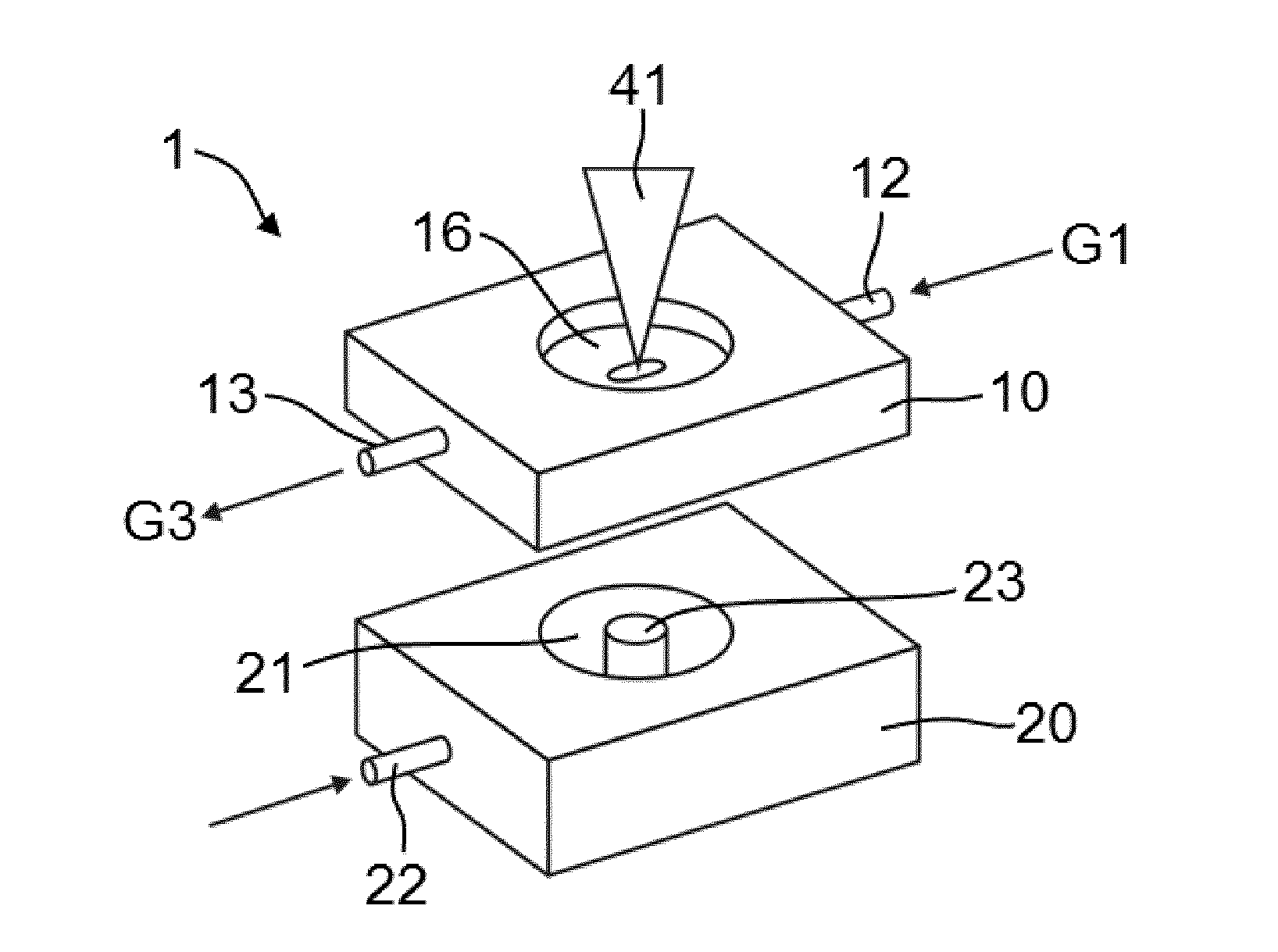
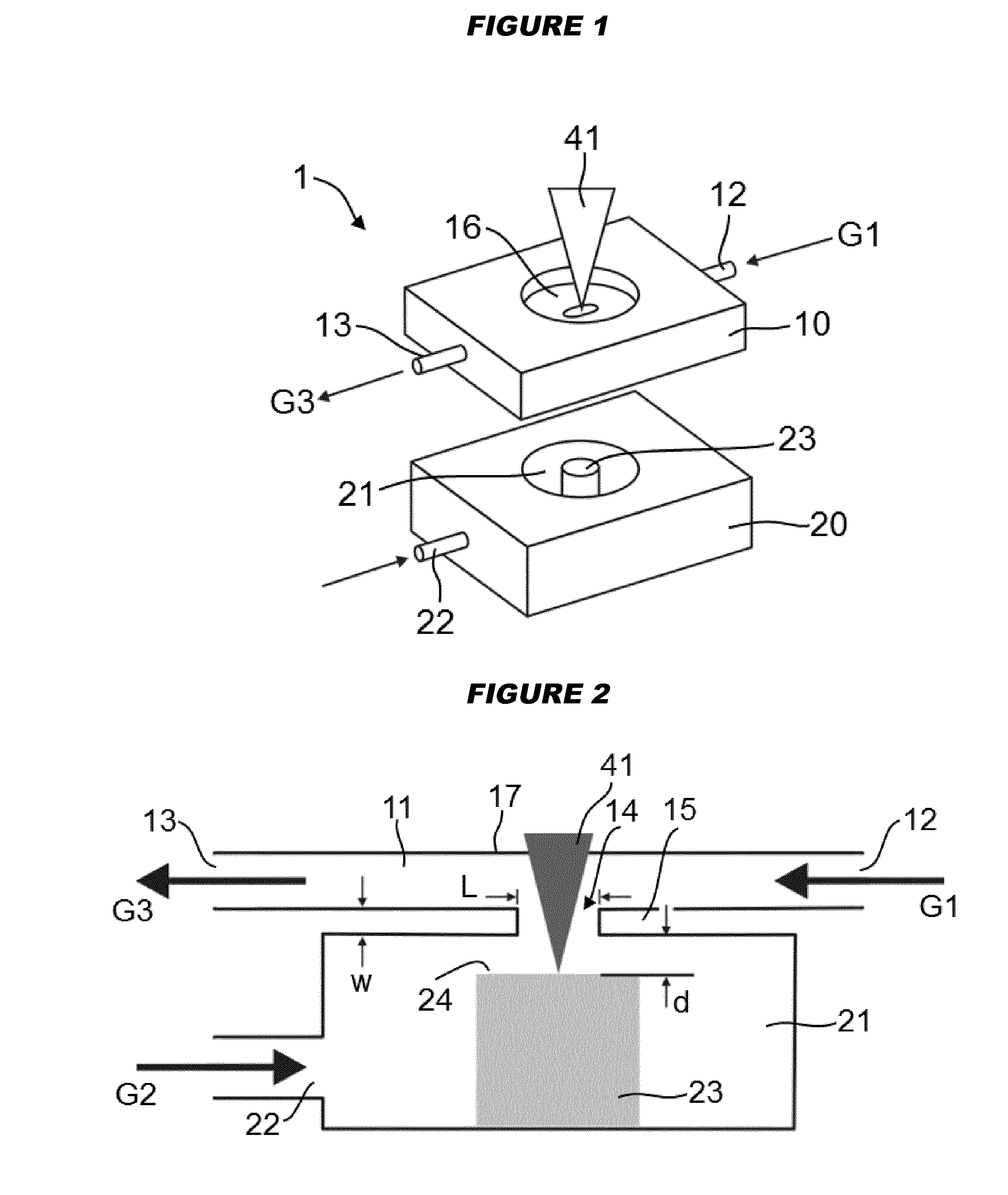
[0101]A cell top 10 was manufactured from a rectangular cuboid of acrylic glass (poly (methyl methacrylate), PMMA). A longitudinal hole of 3 mm inner diameter was drilled through the cuboid along the long axis, forming the flow channel 11. In the top wall portion 17 of the cell top 10, a transversal, slightly elliptically shaped hole with length L=4.5 mm and a width of 1.5 mm was formed and was closed by an UV transparent silica window 16. A lateral opening 14 of similar dimensions as the hole on the top side was formed in the bottom wall portion 15 of the cell top 10. The bottom wall portion 15 was then machined to reduce the minimum thickness w of the bottom wall portion in the region of the flow channel 11 to approximately 50 micrometers. The total length of the flow channel 11 was about 50 mm.

[0102]A cell bottom 10 was manufactured from another PMMA cuboid. A cylindrical sample chamber 21 having a diameter of approxima...


PUM


Abstract

A laser ablation cell (1) comprises a flow channel (11) having an essentially constant cross-sectional area so as to ensure a strictly laminar flow in the flow channel. A sample chamber (21) is provided adjacent to a lateral opening (14) of the flow channel. A laser beam (41) enters the sample chamber (21) through a lateral window (16) and impinges on a surface (24) of a sample (23) to ablate material from the sample. The sample may be positioned in such a distance from the flow channel that the laser-generated aerosol mass distribution has its center within the flow channel. This leads to short aerosol washout times. The laser ablation as cell is particularly well suited for aerosol generation in inductively coupled plasma mass spectrometry (ICPMS), including imaging applications.

Description

TECHNICAL FIELD[0001]The present invention relates to a laser ablation cell, to an ablation apparatus and an inductively coupled plasma (ICP) ion source employing such a laser ablation cell, and to a method of using such a laser ablation cell, for example for the imaging of biological material.BACKGROUND[0002]Inductively coupled plasma mass spectrometry (ICPMS) provides accurate quantitative information on major, minor, trace, and ultra-trace elements of industrial, geological, environmental, and biological samples. In ICPMS, an aerosol sample is carried by a carrier gas stream to a so-called ICP torch. In this torch, the gas is subjected to intense high-frequency electromagnetic fields, which lead to the formation of a plasma by induction. The ions from the plasma are then extracted into a mass spectrometer, where they are separated on the basis of their mass-to-charge ratios.[0003]ICPMS can be coupled with laser ablation (LA) to ablate material from a solid sample so as to create ...

Claims


Application Information

Patent Timeline
Patent Type & Authority Applications(United States)
IPC IPC(8): H01J49/10H01J49/04
CPCH01J49/04H01J49/105H01J49/0463G01N33/57415G01N33/60G01N33/6848H01J49/0004H01J49/0031H01J49/0409H01J49/0459H01J49/40
Inventor GUNTHER, DETLEFGROLIMUND, DANIELWANG, HAO
Owner ETH ZZURICH
Why Eureka
Try Eureka