Environment-protection Energy-saving Barrel

a technology of environmental protection and energy saving, applied in the field of cleaning tools, can solve the problems of loss of link mechanism, and inability to clean the floor at all, and achieve the effects of high market promotion value, convenient repair, and simple and useful structur

Active Publication Date: 2016-02-25
ZHOU ZHONGJIE
View PDF4 Cites 9 Cited by
  • Summary
  • Abstract
  • Description
  • Claims
  • Application Information

AI Technical Summary

Benefits of technology

[0020]According to the environment-protection energy-saving barrel, water in the barrel can be repeatedly used, and water for cleaning the mop is clean each time. Particularly, since the environment-protection energy-saving barrel is provided with the bottom barrel having the multi-stage filtering function, the water in the barrel is recycled, and the barrel is energy-saving and environment-protection. And moreover, the environment-protection energy-saving barrel is in a simple and useful structure, is convenient to repair, and has an extremely high market promoting value.

Problems solved by technology

It apparently seems that the floor has been mopped, but actually, the floor is not clean at all.
The water has a lot of dust, sand and other dirt due to cleaning the mop for many times.
The dewatering basket in the above-mentioned public document 1 plays a main role of dewatering and cleaning dirt, but the structure thereof is very complicated, and long-term use is likely to cause damage and loss of the link mechanism, which is very difficult to maintain for a person not skilled in the art, and the manufacturing cost is higher, which is unacceptable for ordinary people.
However, in the event of mopping the floor, the sewage in the barrel can only be emptied at one time and then clean water is poured into the barrel for water change, which fails to change the condition of mopping the floor with the sewage.

Method used


Image

  • Environment-protection Energy-saving Barrel

Examples


Embodiment Construction

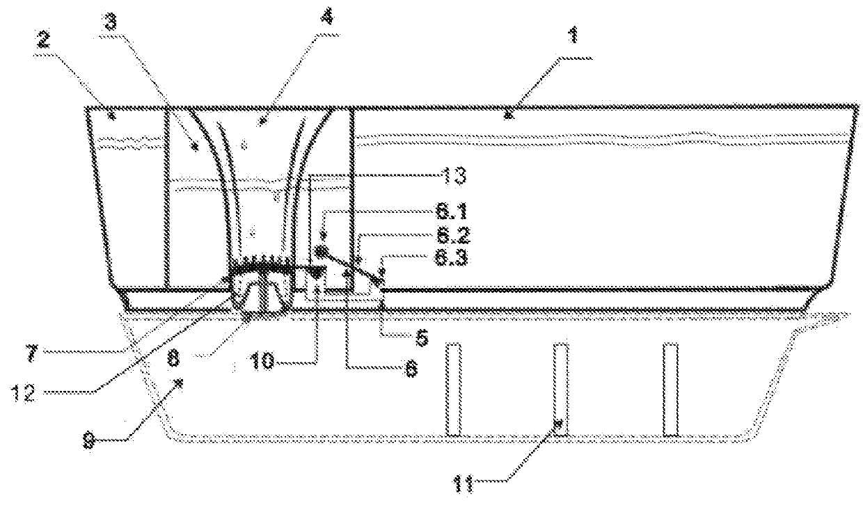
[0025]As shown in FIG. 1, an environment-protection energy-saving barrel according to an embodiment of the present invention includes a barrel body, wherein the barrel body (1) includes three parts, i.e., an outer barrel (2), a middle barrel (3) and an inner barrel (4). The inner barrel (4) is communicated with the middle barrel (3) through a plurality of through holes in the wall between the inner barrel and the middle barrel. The bottom of the middle barrel is provided with a water inlet pipeline (5). The water inlet pipeline is communicated with the bottom of the outer barrel for storing water. One end of the outer barrel is provided with a water inlet quality controller (6) for the water inlet pipeline. The water inlet quantity controller (6) consists of a floater (6.1), a water quantity regulating rod (6.2) and a water outlet valve switch (6.3).

[0026]The floater (6.1) is arranged at one end of the water quantity regulating rod (6.2), and the water outlet valve switch (6.3) arra...


PUM


Abstract

An environment-protection energy-saving barrel is an integral formed by three parts, i.e. an outer barrel, a middle barrel and an inner barrel. The inner barrel is communicated with the middle barrel; the bottom of the middle barrel is provided with a water inlet pipeline; the water inlet pipeline is communicated with the bottom of the outer barrel used for storing water; a water inlet quantity controller is arranged on the water inlet pipeline; the inner barrel communicated with the middle barrel is used for dewatering and cleaning a mop; and the water inlet quantity controller arranged on the water inlet pipeline is used for controlling the water inlet quantity which flows into the middle barrel from the outer barrel and controlling the on/off of a valve of the water inlet pipeline. Therefore the water in the barrel can be repeatedly used.

Description

TECHNICAL FIELD[0001]The present invention relates to a cleaning tool in daily life, and in particular, to an environment-protection energy-saving barrel.BACKGROUND[0002]For a long time, when mopping floors with a mop barrel, only the water for cleaning the mop at the first time is clean as long as the water in the barrel is unchanged; thereafter, the more the mop is washed, the dirtier the floor is. Every time the water in the original barrel is used for washing, and it is finally found that the mop is cleaned with the sewage all the time when mopping the floor. It apparently seems that the floor has been mopped, but actually, the floor is not clean at all.[0003]This is because the water for mopping the floor is unchanged. The water has a lot of dust, sand and other dirt due to cleaning the mop for many times.[0004]Chinese patent public document 1 (publication No. 201445499U) discloses a mop barrel, which consists of a barrel body and a dewatering basket, wherein the interior of th...

Claims


Application Information

Patent Timeline
Patent Type & Authority Applications(United States)
IPC IPC(8): A47L13/58
CPCA47L13/58A47J47/18A47L13/59
Inventor ZHOU, ZHONGJIE
Owner ZHOU ZHONGJIE
Why Eureka
Try Eureka