

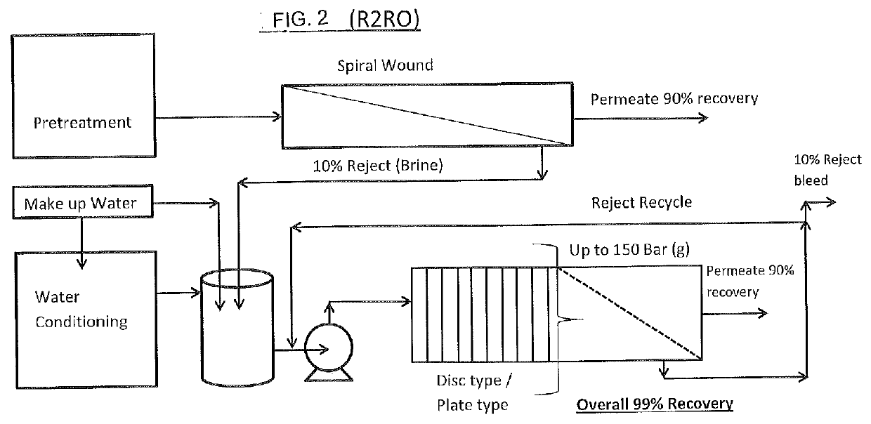
Reject recovery reverse osmosis (R2RO)
a reverse osmosis and water treatment technology, applied in the direction of multi-stage water/sewage treatment, membranes, other chemical processes, etc., can solve the problems of inability to process, reduced water recovery rate, and reduced water recovery efficiency, so as to improve the overall recovery of the system
- Summary
- Abstract
- Description
- Claims
- Application Information
AI Technical Summary
Benefits of technology
Problems solved by technology
Method used
Image

Examples
examples
[0056]Embodiments of the invention may be better understood by reference to examples and to the figures included herein. An extended study was done on a reject stream of the operating reverse osmosis unit. The base reverse osmosis was operating at 85-90% recovery at different times. The new process was employed with the reject stream, which was being generated by the existing RO. The reject stream was highly concentrated with contaminants to such and extent that it would foul a hollow fiber UF membrane and spirally would RO membrane if we attempt any further water recovery. All the attempts to use a conventional process failed to give any results and experiments were performed with the new process.
[0057]The reject was essentially rich in COD and dissolved oil and had high turbidity. The new process had configuration as depicted in the process flow diagram at FIG. 8. The recovery across the reject stream RO unit was slowly ramped up from 65% to 90% over 14 experiments followed by ano...
PUM
| Property | Measurement | Unit |
|---|---|---|
| pressure | aaaaa | aaaaa |
| pressures | aaaaa | aaaaa |
| concentration | aaaaa | aaaaa |
Abstract
Description
Claims
Application Information