System and console for monitoring and managing well site drilling operations

Active Publication Date: 2016-02-25
KONGSBERG OIL & GAS TECH
View PDF8 Cites 33 Cited by
  • Summary
  • Abstract
  • Description
  • Claims
  • Application Information

AI Technical Summary

Benefits of technology

[0026]In one embodiment, the system comprises a Drilling Operations Console integrateing several functions into a single console, including, but not limited to, wellbore stability and hole cleaning. It also may incorporate elements regarding rate of penetration (ROP) and rig site fluid management (RSFM). The Drilling Operations console may be used by drillers, drilling engineers, well site leaders, drilling experts, mud loggers, logging while drilling (LWD) engineers, operations geologists, and similar support personnel. It provides users with information enabling them to quickly respond to events happening in the wellbore, and make drilling d

Problems solved by technology

It is well-known that the drilling of an oil or gas well, and related operations, is responsible for a significant portion of the costs related to oil and gas exploration and production.
In particular, as new wells are being drilled into remote or less-accessible reservoirs, the complexity, time and expense to drill a well have substantially increased.
With directional drilling techniques, and the greater depths to which wells are being drilled, many complexities are added to the drilling operation, and the cost and effort required to respond to a problem during drilling are high.
In many cases, the initial geological model may be inaccurate.
Further, since some geological models recite distances based on the distance between two tops, an error in the absolute depth of one top can result in errors in the depths of multiple tops.
Such errors thus affect safety as well as cost and efficiency.
In some cases, the penetration of a high pressure formation can cause a sudden pressure increase (or “kick”) in the wellbore.
If not detected and controlled, a “blowout” can occur, which may result in failure of the well.
Conversely, if the mud weight is too

Method used


Image

  • System and console for monitoring and managing well site drilling operations
  • System and console for monitoring and managing well site drilling operations
  • System and console for monitoring and managing well site drilling operations

Examples


Embodiment Construction

Computing Environment Context

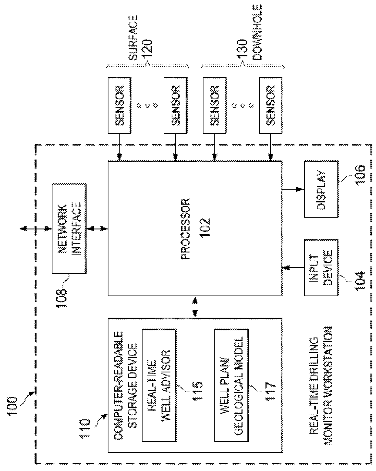
[0056]The following discussion is directed to various exemplary embodiments of the present invention, particularly as implemented into a situationally-aware distributed hardware and software architecture in communication with one or more operating drilling rigs. However, it is contemplated that this invention may provide substantial benefits when implemented in systems according to other architectures, and that some or all of the benefits of this invention may be applicable in other applications. For example, while the embodiments of the invention may be described herein in connection with wells used for oil and gas exploration and production, the invention also is contemplated for use in connection with other wells, including, but not limited to, geothermal wells, disposal wells, injection wells, and many other types of wells. One skilled in the art will understand that the examples disclosed herein have broad application, and that the discussion of any...


PUM


Abstract

A well advisor system and console for monitoring and managing drilling operations at a well site. The system may be accessed through one or more workstations, or other computing devices, which may be located at a well site or remotely. The system is in communication with and receives input from various sensors. It collects real-time sensor data sampled during operations at the well site. The system processes the data, and provides nearly instantaneous numerical and visual feedback through a variety of graphical user interfaces (“GUIs”), which are presented in the form of an operation-specific console. The input and data provides information related to drilling operations at a well site, including, but not limited to, hole cleaning status and wellbore stability.

Description

[0001]This application claims benefit of and priority to U.S. Provisional Application No. 61 / 987,825, filed May 2, 2014, and is entitled to benefit of that priority date. The specification, figures, appendices and complete disclosure of U.S. Provisional Application No. 61 / 987,825 are incorporated herein in their entireties by specific reference for all purposes.FIELD OF INVENTION[0002]This invention relates generally to oil and gas well drilling and production, and related operations. More particularly, this invention relates to a computer-implemented system for monitoring and managing the performance of well drilling operations.BACKGROUND OF THE INVENTION[0003]It is well-known that the drilling of an oil or gas well, and related operations, is responsible for a significant portion of the costs related to oil and gas exploration and production. In particular, as new wells are being drilled into remote or less-accessible reservoirs, the complexity, time and expense to drill a well ha...

Claims


Application Information

Patent Timeline
IPC IPC(8): E21B45/00E21B47/00G05B15/02
CPCE21B45/00E21B47/00G05B15/02E21B44/00
Inventor ABBASSIAN, FEREIDOUNANDRESEN, PER ARILDHONEY, MARK ADRIANMCKAY, JAMESREINERTSEN, TERJE SORLIESKARBO, RUNE ARNTASTON, MARK SHELTONCOLEY, CHRISTOPHER JEREMYEDWARDS, STEPHEN TEANLAST, NIGEL CHARLESLOCKYEAR, CHRISTOPHER FRANCISMASON, COLIN JAMESPAYNE, MICHAEL LYLEWAAGE, TRONDWHITELEY, NICHOLAS ADAMWINTERS, WARREN JEFFREYNAIDU, RAJARAJAN NARAYANASAMY
Owner KONGSBERG OIL & GAS TECH
Why Eureka
Try Eureka