Flip-flop for reducing dynamic power

Active Publication Date: 2016-02-25
QUALCOMM INC
View PDF6 Cites 7 Cited by
  • Summary
  • Abstract
  • Description
  • Claims
  • Application Information

AI Technical Summary

Benefits of technology

[0011]A flip-flop circuit is disclosed that may reduce dynamic power consumption as compared to conventional flip-flop circuits such as the flip-flop circuit 100 of FIG. 1. In accordance with the present embodiments, the flip-flop circuit may include a first latch and a second latch. The first latch, which may operate as a “master” latch, includes a first input terminal to receive a data signal, a second input terminal to receive a clock signal, and an output terminal. The second latch, which may operate as a “slave” latch, include

Problems solved by technology

Dynamic power consumption is an ongoing concern for integrated circuit (IC) devices, especially with the ever-increasing clock frequencies used in synchronous IC devices.
These inverter circuits, as well as the pass gates and tri-state circuits, consume dynamic power every time the clock signal transitions between logic states.
As a result, these conventional flip-flops may consume a significant amount of dynamic power even when switching activity is relatively low.
The inverters IN

Method used


Image

  • Flip-flop for reducing dynamic power
  • Flip-flop for reducing dynamic power
  • Flip-flop for reducing dynamic power

Examples


Embodiment Construction

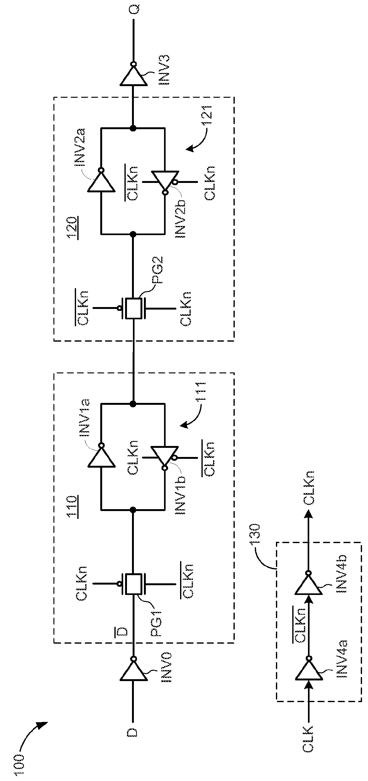
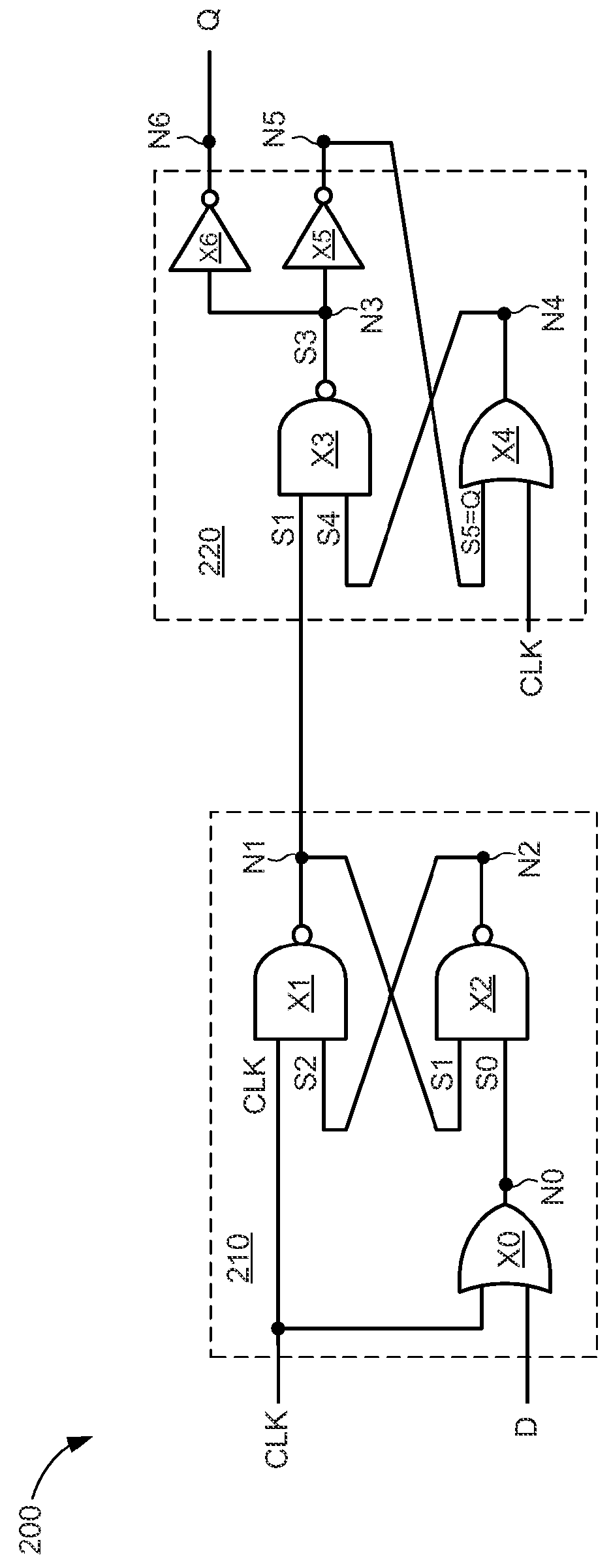
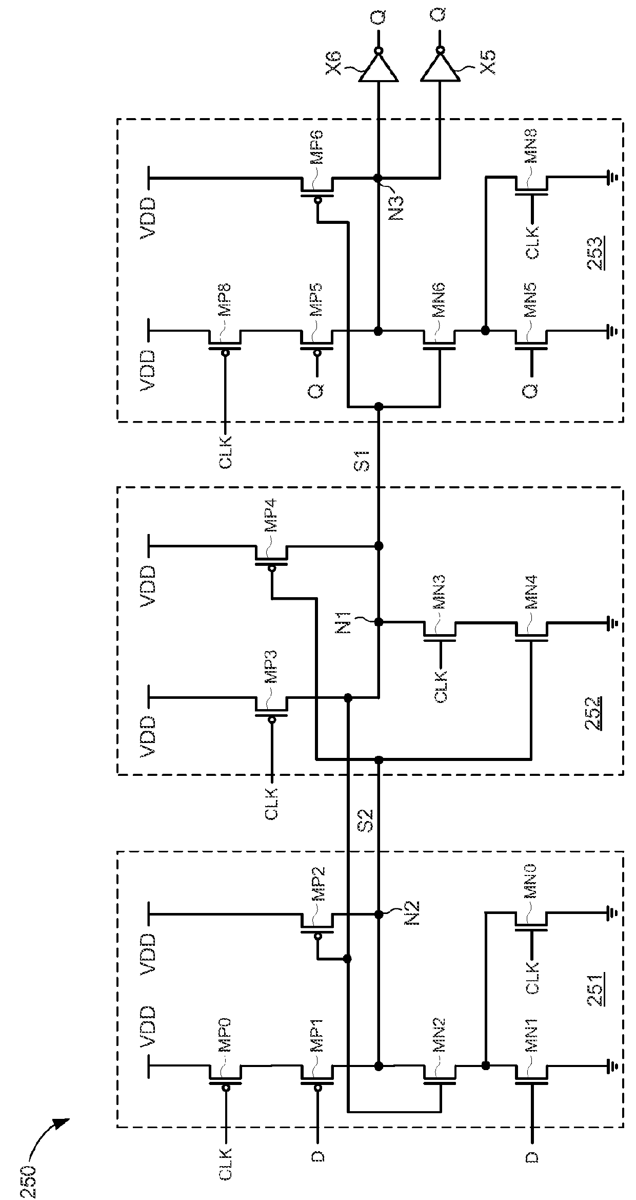
[0025]The present embodiments are discussed below in the context of a data type flip-flop circuit for simplicity only. It is to be understood that the present embodiments are equally applicable to other types of flip-flop circuits (e.g., such as set-reset (SR) flip-flops and JK flip-flops). In the following description, numerous specific details are set forth such as examples of specific components, circuits, and processes to provide a thorough understanding of the present disclosure. Also, in the following description and for purposes of explanation, specific nomenclature is set forth to provide a thorough understanding of the present embodiments. However, it will be apparent to one skilled in the art that these specific details may not be required to practice the present embodiments. In other instances, well-known circuits and devices are shown in block diagram form to avoid obscuring the present disclosure. The term “coupled” as used herein means connected directly to or connecte...


PUM


Abstract

A flip-flop circuit may include a first latch and a second latch. The first latch, which may operate as a “master” latch, includes a first input terminal to receive a data signal, a second input terminal to receive a clock signal, and an output terminal. The second latch, which may operate as a “slave” latch, includes a first input terminal connected directly to the output terminal of the first latch, a second input terminal to receive the clock signal, and an output terminal to provide an output signal. The first latch and the second latch are to be clocked on the same phase of the clock signal, thereby eliminating the need to include clock inversion circuits that generate complementary clock signals.

Description

TECHNICAL FIELD[0001]The present embodiments relate generally to electronic circuits, and specifically to flip-flop circuits.BACKGROUND OF RELATED ART[0002]Dynamic power consumption is an ongoing concern for integrated circuit (IC) devices, especially with the ever-increasing clock frequencies used in synchronous IC devices. For some IC devices, more than half of the total dynamic power consumption may be attributed to clock distribution networks and flip-flop circuits. Many conventional flip-flops employ inverter circuits to generate complementary clock signals for use by various pass gates and / or tri-state circuits that form the latches and / or gating circuits within the flip-flops. These inverter circuits, as well as the pass gates and tri-state circuits, consume dynamic power every time the clock signal transitions between logic states. As a result, these conventional flip-flops may consume a significant amount of dynamic power even when switching activity is relatively low.[0003...

Claims


Application Information

Patent Timeline
IPC IPC(8): H03K3/3562
CPCH03K3/35625H03K3/012
Inventor CAI, YANFEIDAI, QIANGHUANG, SHUANGQU
Owner QUALCOMM INC
Why Eureka
Try Eureka