Chain tensioner

a chain tensioner and tensioner technology, applied in the direction of belts/chains/gearrings, mechanical equipment, belts/chains/gears, etc., can solve the problems of difficulty in holding the operation tool in the state of the pair of operating portions, low work efficiency, and difficulty in maintenance work, so as to increase the length of the arc and reduce the diameter of the elastic ring member. , the effect of increasing the ar

Active Publication Date: 2016-03-03
TSUBAKIMOTO CHAIN CO
View PDF9 Cites 4 Cited by
  • Summary
  • Abstract
  • Description
  • Claims
  • Application Information

AI Technical Summary

Benefits of technology

[0016]Moreover, due to the operating portions of the elastic ring member protruding in a direction of the maintenance hole from the tensioner body (a direction opposite to the mounting surface to the engine or the like), a space corresponding to the protrusion must be secured as a mounting space of the chain tensioner, thereby inhibiting downsizing of the engine or the like in which the chain tensioner is used.
[0025]With the configuration according to present claim 6, due to the first arm portions of the pair of operating portions being formed so as to extend while being inclined with respect to one another, the diameter of the elastic ring member can be enlarged without causing the pair of operating portions to come into contact with each other. As a result, the diameter of the elastic ring member can be reliably enlarged without causing twisting of the annular elastic portion, an engagement with the annular grooves of the plunger can be reliably released when the diameter of the elastic ring member is enlarged, and work efficiency can be improved.

Problems solved by technology

Since these operations involve operating a pair of pliers or a dedicated operation tool through a small maintenance hole, there is a problem that work efficiency is low.
In addition, since maintaining the annular elastic portion in a diameter-enlarged state requires continuously operating the pair of operating portions using the pair of pliers or the dedicated operation tool, there is also a problem that maintenance work consumes time.
In addition, in the case of an elastic ring member of a type in which a pair of operating portions do not intersect each other, since positions of both operation portions are susceptible to change due to a gap that exists between a notched portion and the pair of operating portions, there is a problem that an operation involving inserting the operation tool between the pair of operating portions and holding the operation tool in that state is difficult.

Method used


Image

  • Chain tensioner
  • Chain tensioner
  • Chain tensioner

Examples


embodiment

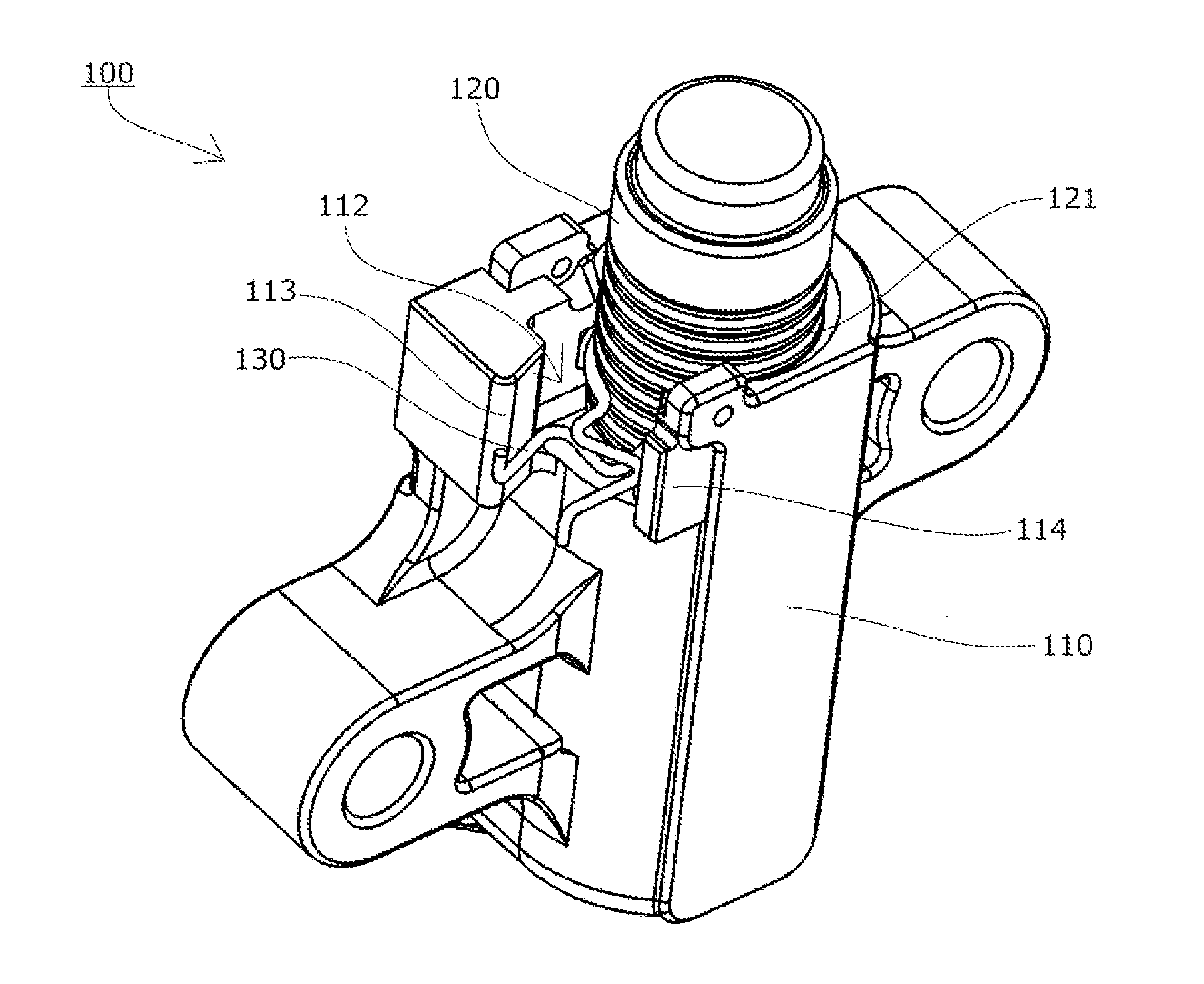
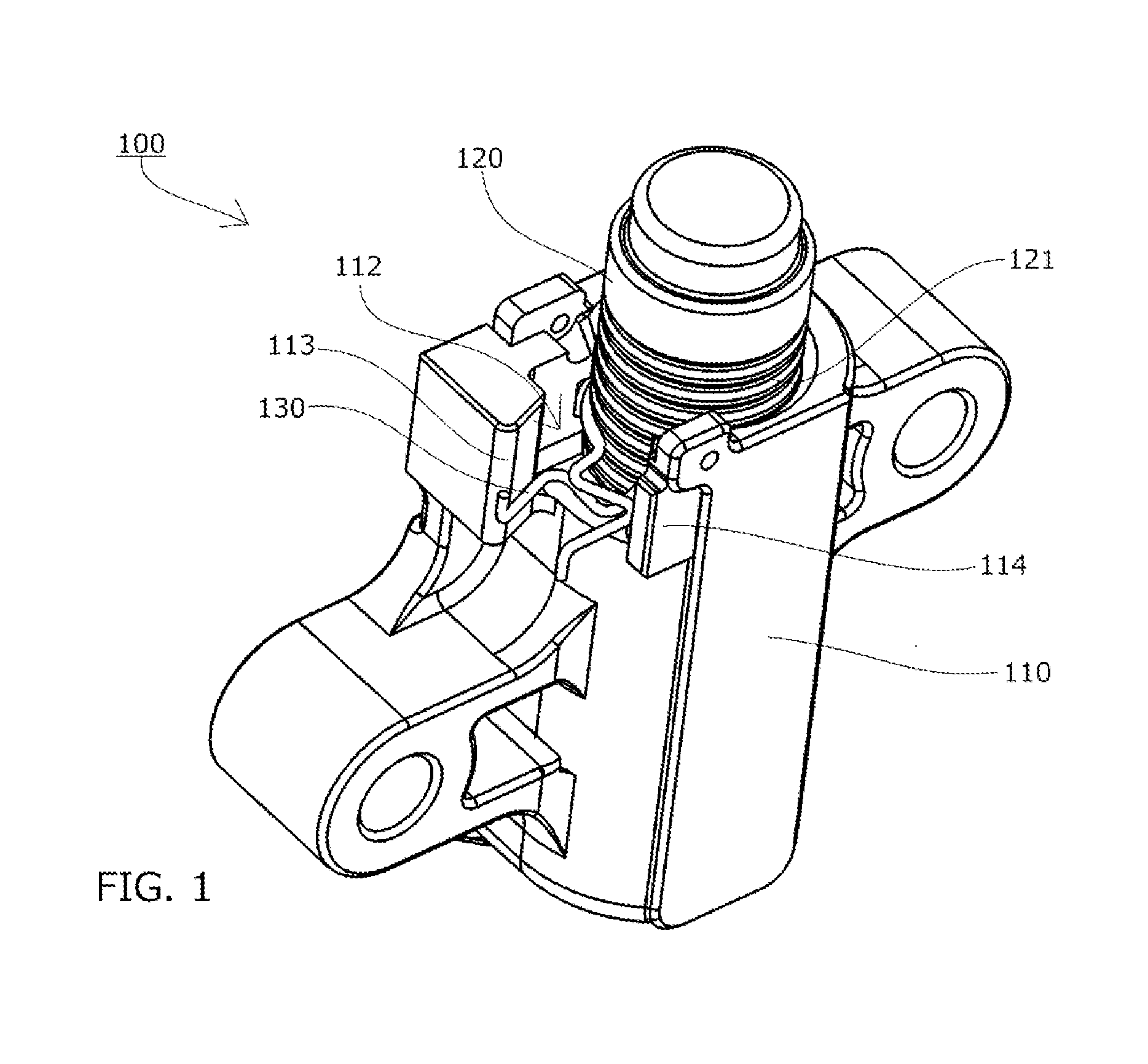
[0038]As shown in FIGS. 1 to 10, a chain tensioner 100 according to an embodiment of the present invention includes a tensioner body 110 having a plunger housing hole 111 opened at one end, a cylindrical plunger 120 to be slidably inserted into the plunger housing hole 111, and biasing means (not shown) such as a spring mechanism or a hydraulic mechanism that biases the plunger 120 in a protruding direction.

[0039]As shown in FIGS. 1 to 5 and 7, the plunger 120 includes a plurality of annular grooves 121 that are engageable by an elastic ring member 130 on an outer peripheral surface of the plunger 120.

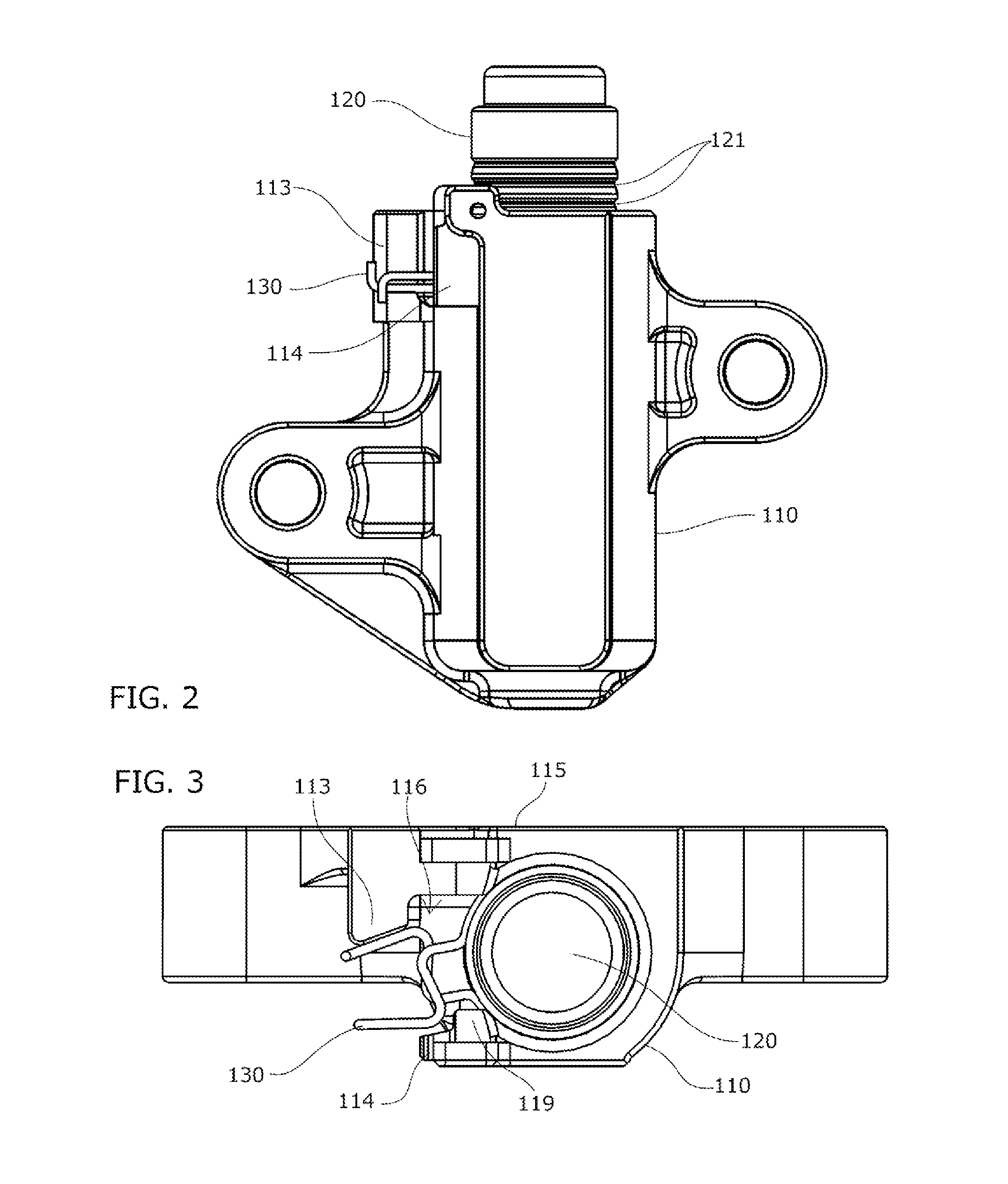
[0040]A ring holding portion 112 that holds the elastic ring member 130 is provided on an open side of the plunger housing hole 111 of the tensioner body 110.

[0041]In addition, a mounting surface 115 that enables the tensioner body 110 to be mounted to an engine or the like is formed on one surface on an outer periphery of the tensioner body 110.

[0042]As shown in FIGS. 8 to 10, the ela...


PUM


Abstract

An object of the present invention is to provide a chain tensioner which enables operations on an elastic ring member during assembly and maintenance work to be readily performed and which is capable of eliminating protrusion of an operating portion of the elastic ring member in a direction opposite to a mounting surface, with a simple configuration. A ring holding portion 112 provided on an open side of a plunger housing hole 111 includes a pressing projection 113 and a restricting portion 114 which restrict rotation of the elastic ring member 130 and which oppose both outer sides of a pair of operating portions 132 of the elastic ring member 130 in a circumferential direction, and the pressing projection 113 is arranged at a position closer to a mounting surface 115 than the restricting portion 114.

Description

BACKGROUND OF THE INVENTION[0001]1. Field of the Invention[0002]The present invention relates to a chain tensioner which includes a tensioner body having a plunger housing hole opened at one end, a cylindrical plunger to be slidably inserted into the plunger housing hole, and biasing means for biasing the plunger in a protruding direction, and which holds tension of a chain at a proper value.[0003]2. Description of the Related Art[0004]Conventionally, it is common practice to use a chain tensioner that holds tension of a chain at a proper value. For example, there is a known chain guide mechanism that uses a travel guide shoe to slidingly guide a transmission chain such as a roller chain being endlessly wound around sprockets respectively provided on a crankshaft and a camshaft inside an engine room, wherein a swinging chain guide that includes the travel guide shoe is biased by a chain tensioner in order to hold tension of the chain at a proper value.[0005]For example, as shown in ...

Claims


Application Information

Patent Timeline
Patent Type & Authority Applications(United States)
IPC IPC(8): F16H7/08
CPCF16H2007/0802F16H7/0848F16H7/08F16H7/18
Inventor TAKAGI, YASUYUKIYOSHIDA, OSAMUKUREMATSU, YUJI
Owner TSUBAKIMOTO CHAIN CO
Why Eureka
Try Eureka