Probe for an Optoacoustic Imaging Device
a technology of optoacoustic imaging and probes, which is applied in the field of probes for optoacoustic imaging devices, can solve the problems of large system size of lasers, disadvantage in cost, and high cost of solid-state lasers, and achieve the effect of cost advantag
- Summary
- Abstract
- Description
- Claims
- Application Information
AI Technical Summary
Benefits of technology
Problems solved by technology
Method used
Image
Examples
first embodiment
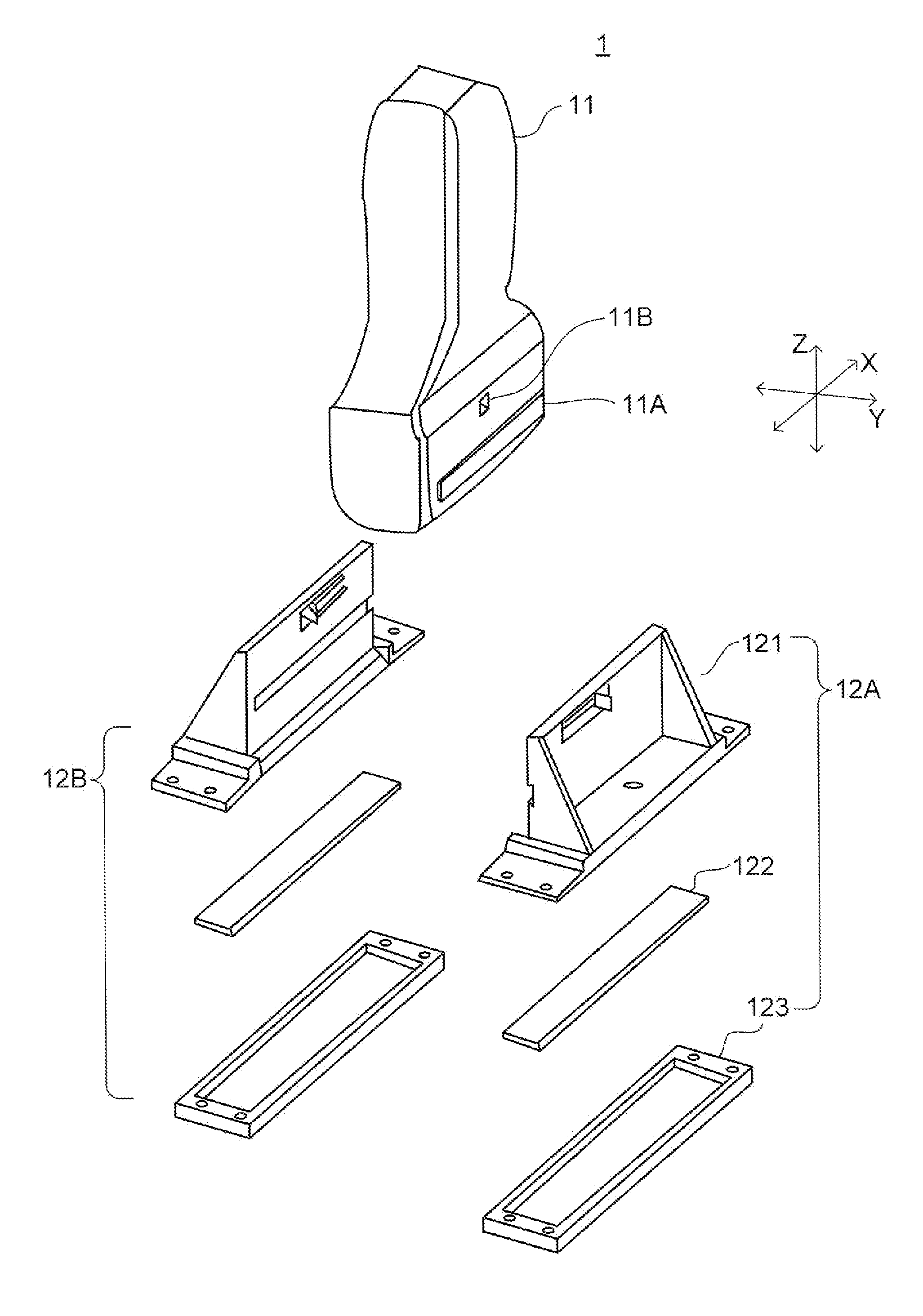
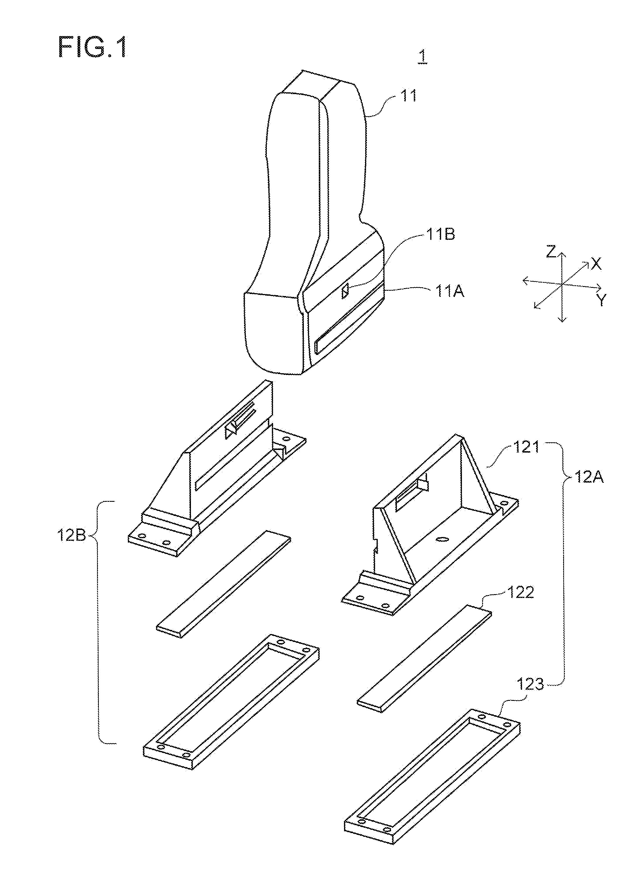
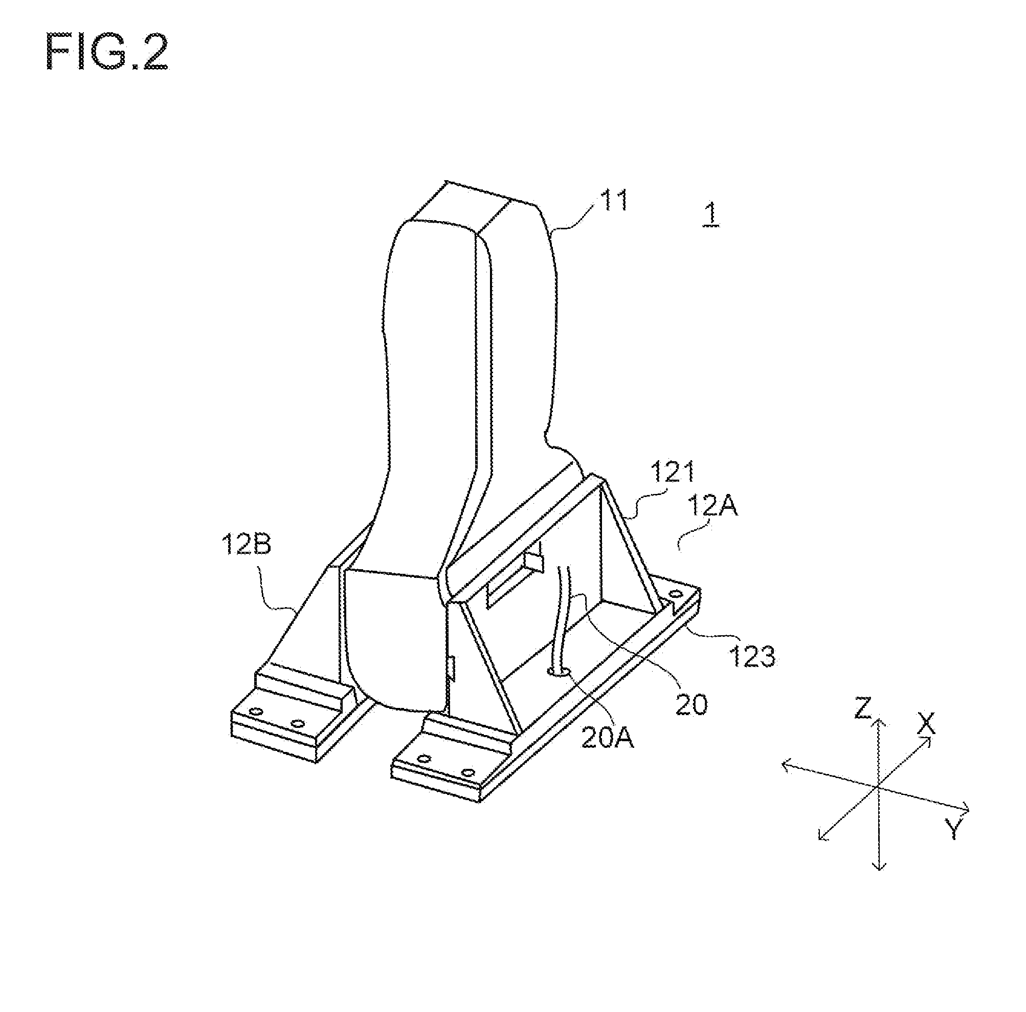
[0052]Hereinafter, embodiments of the present invention will be described with reference to the accompanying drawings. First, a first embodiment of the present invention will be described. An explosive perspective view of a probe for an optoacoustic imaging device (hereinafter “optoacoustic probe”) according to the first embodiment is shown in FIG. 1, and a perspective view of the optoacoustic probe put together is shown in FIG. 2. The configuration of an optoacoustic imaging device provided with an optoacoustic probe embodying the present invention will be described later.
[0053]The optoacoustic probe 1 shown in FIGS. 1 and 2 includes an ultrasonic wave probe 11 which emits an ultrasonic wave into a tested object (living body) and detects the ultrasonic wave reflected inside the tested object, and irradiation units 12A and 12B which irradiate the tested object with light. Here, the ultrasonic wave probe 11 is assumed to be of a so-called linear type, but this is not meant as any lim...
second embodiment
[0088]The first embodiment described above allows for various modifications, of which some examples will be described below, starting with a second embodiment of the present invention. A roughly exploded perspective view of an optoacoustic probe according to the second embodiment is shown in FIG. 7, and a perspective view of the optoacoustic probe put together is shown in FIG. 8.
[0089]The optoacoustic probe 2 shown in FIGS. 7 and 8 includes an ultrasonic wave probe 21 and irradiation units 22A and 22B. The front and rear faces of the housing of the ultrasonic wave probe 21 are each provided with a hook 21A and a boss 21B for positioning. The irradiation unit 22A (and 22B) is composed of an upper light source cover 221, a lower light source cover 223, and an LED light source (unillustrated) housed inside a case composed of the former two.
[0090]Now, the structure of the upper light source cover 221 will be described in detail. FIG. 9 is a rear perspective view of the upper light sourc...
third embodiment
[0095]Next, a third embodiment of the present invention will be described. An explosive perspective view of an optoacoustic probe according to the third embodiment is shown in FIG. 12, and a perspective view of the optoacoustic probe put together is shown in FIG. 13.
[0096]The optoacoustic probe 3 shown in FIGS. 12 and 13 includes an ultrasonic wave probe 31 and an irradiation unit 32. The irradiation unit 32 is composed of an upper light source cover 321, two LED light sources 322, and two lower light source covers 323. The LED light sources 322 are mounted on the lower light source covers 323 respectively, which are then sealed by the upper light source cover 321 to accommodate the LED light sources 322 inside.
[0097]The front and rear faces of the ultrasonic wave probe 31 are each provided with bosses 31A for positioning. The upper light source cover 321 includes a base 321A and clamps 321B and 321C, the latter being connected to the former so as to be pivotable about hinges H5 and...
PUM
 Abstract
Description
Claims
Application Information
 - R&D
- Intellectual Property
- Life Sciences
- Materials
- Tech Scout
- Unparalleled Data Quality
- Higher Quality Content
- 60% Fewer Hallucinations
Browse by: Latest US Patents, China's latest patents, Technical Efficacy Thesaurus, Application Domain, Technology Topic, Popular Technical Reports.
© 2025 PatSnap. All rights reserved.Legal|Privacy policy|Modern Slavery Act Transparency Statement|Sitemap|About US| Contact US: help@patsnap.com


