Target substance capturing device

a technology of capturing device and target substance, which is applied in the direction of material analysis, material analysis using immobilised reagents, instruments, etc., can solve the problem of small cycle of lattice pattern of reflection surface, and achieve the effect of enhancing sensor sensitivity, reducing noise in measurement, and improving s/n ratio

Active Publication Date: 2016-03-03
NSK LTD
View PDF3 Cites 2 Cited by
  • Summary
  • Abstract
  • Description
  • Claims
  • Application Information

AI Technical Summary

Benefits of technology

[0020]According to further aspect of the invention, a cross section of the non-flat portion along the reflection surface is circle, and a diameter of the cross section of the non-flat portion is one time or less a length of one side of the regular triangle. Accordingly, the adjacent non-flat portions become not in contact with each other. Therefore, the shape of the non-flat portion can be easily kept.
[0021]According to further aspect of the invention, a length of one side of the regular triangle is 0.5 times a minimum distance between the intersections of the lattice pattern, and the one side of the regular triangle is parallel to a straight line included in the lattice pattern. Accordingly, non-flat portions 28A are arranged in a direction of a lattice pattern La at regular intervals, so that a cycle of the lattice pattern La is less likely to be disordered. Therefore, a half-value width of the shape of a spectrum of the reflected light becomes small, and a noise in measurement can be decreased. Therefore, the S / N ratio can be improved, and the target substance capturing device can enhance the sensor sensitivity.
[0022]According to further aspect of the invention, a cross section of the non-flat portion along the reflection surface is a regular hexagon or a star shape. The shape of the cross section has six-time rotational symmetry. Therefore, by causing the non-flat portion to have such a shape, the target substance capturing device according to the present invention can realize further improvement of measurement accuracy because the shape of the non-flat portion has six-time symmetry, in addition to the arrangement of the non-flat portions is the six-time symmetry.
[0023]By use of the target substance capturing device of the present invention, the sensor sensitivity can be enhanced while the cycle of the lattice pattern of the reflection surface can be a desired value. The target substance detecting device including the target substance capturing device of the present invention can enhance the sensor sensitivity while causing the cycle of the lattice pattern of the reflection surface to be a desired value.

Problems solved by technology

However, if the number of the recessed portions is simply increased, the cycle of a lattice pattern of the reflection surface becomes small.

Method used


Image

  • Target substance capturing device
  • Target substance capturing device
  • Target substance capturing device

Examples


first embodiment

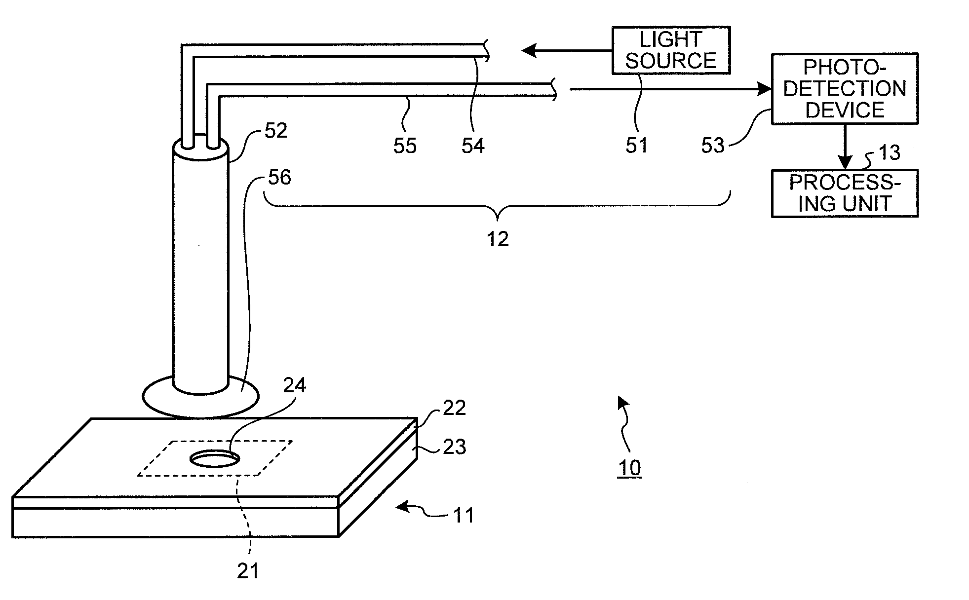
[0062]A target substance detecting device including a target substance capturing device according to a first embodiment will be explained. FIG. 1 is a diagram illustrating a target substance detecting device. A target substance detecting device 10 includes a photonic crystal biosensor (target substance capturing device) 11 according to the first embodiment, a photo-detection section 12, and a processing unit 13.

[0063](Photonic Crystal Biosensor)

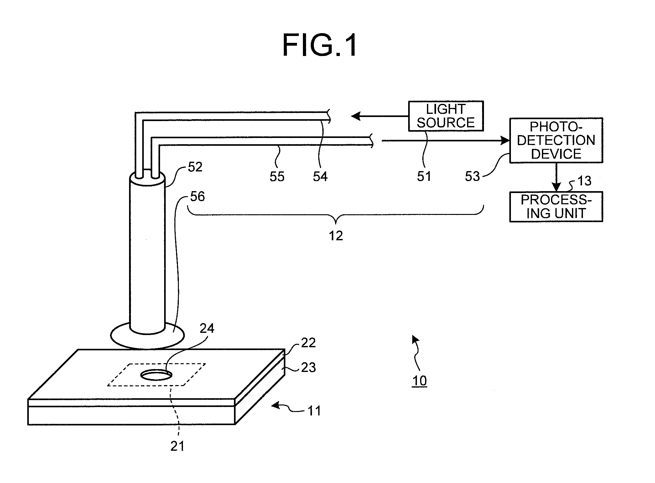
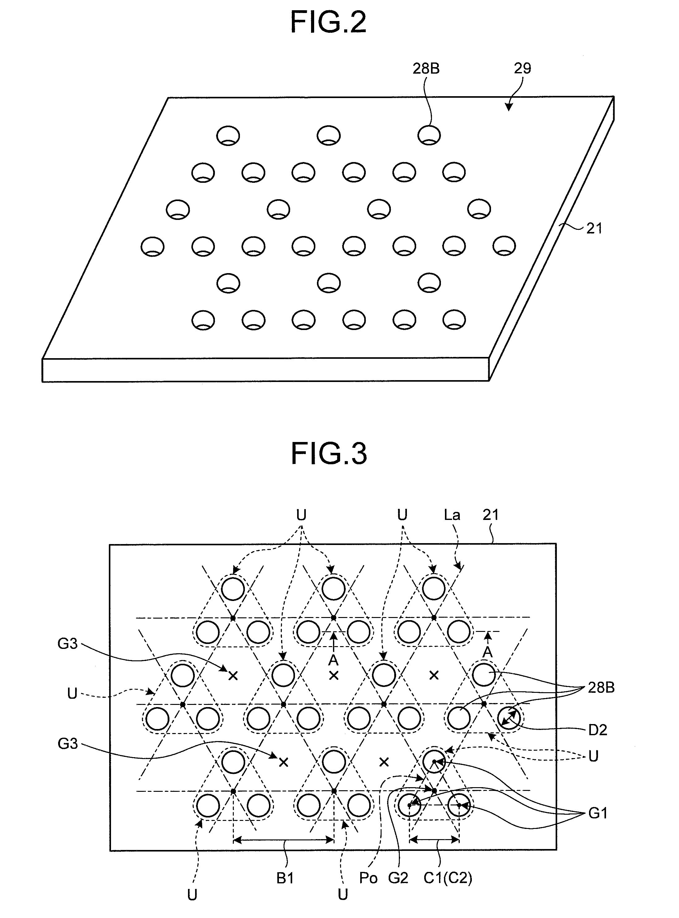
[0064]First, the photonic crystal biosensor 11 will be explained. The photonic crystal biosensor 11 includes a metal-film coated photonic crystal 21, an upper plate 22, and a lower plate 23. The upper plate 22 is provided with an opening 24. In the first embodiment, the photonic crystal biosensor 11 has a structure in which the metal-film coated photonic crystal 21 is sandwiched by the upper plate 22 and the lower plate 23. Note that, in the first embodiment, the photonic crystal biosensor 11 is formed to include the upper plate22 and the low...

second embodiment

[0158]A target substance detecting device including a target substance capturing device according to a second embodiment will be explained. The target substance capturing device according to the second embodiment is similar to that of the first embodiment, except a change that an antigen (target substance) 36 is fixed to a reflection surface 29 of a metal-film coated photonic crystal 21, and an antibody 34 is absorbed by the antigen 36, and thus overlapping description is omitted.

[0159]FIGS. 27 to 31 are diagrams for describing a principle of a photonic crystal biosensor. Description will be given using cortisol as the antigen 36, and an anti-cortisol antibody as the antibody 34, in the second embodiment, as a special reaction between the antibody 34 and the antigen 36.

[0160]First, as illustrated in FIG. 27, as a means for fixing the antigen 36 to the reflection surface 29a of the metal-film coated photonic crystal biosensor 11, the metal-film coated photonic crystal biosensor 11 ca...

third embodiment

[0171]FIG. 33 is a cross-sectional view of a metal-film coated photonic crystal according to a third embodiment cut in a plane perpendicular to a reflection surface. As illustrated in FIG. 33, in the third embodiment, non-flat portions 28Ac and 28Bc are conically recessed portions depressed in a surface 27. Accordingly, when a metal-film coated photonic crystal 21 is manufactured using a die and a resin, by heat nanoimprint, the die can be easily released from the resin. Therefore, the non-flat portions 28Ac and 28Bc can be more easily formed than the non-flat portions 28A and 28B that are the columnar recessed portions of the first embodiment. Therefore, the metal-film coated photonic crystal 21 according to the third embodiment can be easily manufactured.

[0172]Note that, in the above description, the non-flat portion according to the third embodiment is the recessed portion as illustrated in FIG. 33. However, the non-flat portion may be a protruding portion. The non-flat portions ...


PUM

PropertyMeasurementUnit
angleaaaaaaaaaa
diameter D1aaaaaaaaaa

Abstract

A target substance capturing device includes a reflection surface on which a plurality of non-flat portions is arrayed, the reflection surface capturing a target substance, and reflecting irradiated light. The plurality of non-flat portions are arranged in an array, the array includes a plurality of unit arrays in which the plurality of non-flat portions are arranged such that each one center of the non-flat portions superposes a position of a vertex in an M-time symmetrical figure, and the plurality of unit arrays is arranged such that each one center of gravity of the M-time symmetrical figure superposes a position of an intersection of an N-time symmetrical lattice pattern, where M is an integer of two or more, and N is an integer of two or more and different from M.

Description

BACKGROUND OF THE INVENTION[0001]1. Field of the Invention[0002]The present invention relates to a target substance capturing device that detects a target substance.[0003]2. Description of the Related Art[0004]As means to detect a target substance such as protein or a cell, or to measure the concentration, biosensors using a photonic crystal are known (for example, Non Patent Literature 1 (hereinafter, Prior Art 2)). The biosensors described in Prior Art 2 irradiate a photonic crystal substrate on which a gold thin film is formed, with light, and measure reflected light reflected at the photonic crystal substrate, thereby to detect the target substance, measure the concentration of the target substance, and the like. Patent Literature 1 (herein after, Prior Art 1) describes a biosensor having a reflection surface on which columnar protruding portions are uniformly arrayed in a square lattice shape, that is, in an arrangement having one rotational symmetry, as an uneven structure. No...

Claims


Application Information

Patent Timeline
Patent Type & Authority Applications(United States)
IPC IPC(8): G01N33/53G01N21/552G01N21/75
CPCG01N21/01G01N21/41G01N33/5302G01N21/75G01N21/553G01N21/554G01N2021/757G01N21/7743B82Y5/00
Inventor YOKOYAMA, KEISUKEFURUKAWA, HIDEKIOKUTANI, NOBUKOSASAO, KUNIHIKOOGUCHI, TOSHIAKI
Owner NSK LTD
Why Eureka
Try Eureka