
In-vehicle imaging device

a technology for imaging devices and vehicles, applied in the field of vehicles, can solve problems such as difficult to accurately detect corneal reflection, image sensors, and difficult to accurately acquire face images

Inactive Publication Date: 2016-03-03
ALPS ALPINE CO LTD
View PDF5 Cites 10 Cited by
  • Summary
  • Abstract
  • Description
  • Claims
  • Application Information

AI Technical Summary

Benefits of technology

The in-vehicle imaging device described in this patent has a camera that takes pictures of a passenger's eyes. A control unit processes these pictures. The control unit has a feature that automatically adjusts the camera's exposure based on the brightness of the outside light. This ensures that the camera always captures pictures with the best possible quality. The control unit also stores multiple exposure settings for different light levels, so the control unit can select the best setting for any given situation. Overall, this technology makes it much easier to take pictures in the dark or during bright sunny weather.

Problems solved by technology

In addition, in this type of pupil detection method, in some cases it is difficult to correctly acquire a face image, owing to a surrounding light environment such as sunlight, and in some cases it is difficult to correctly detect the corneal reflection.
While it is considered that the pupil detection method described in Japanese Unexamined Patent Application Publication No. 2008-246004 is insusceptible to the surrounding light environment, it is necessary to use a special camera that utilizes the half mirror and the two image sensors and the structure thereof becomes complex.
In addition, since, in addition to the bright pupil image and the dark pupil image, it is necessary to obtain the non-illuminated image, the setting of the acquisition timing of an image or the like becomes difficult.
In addition, while this type of pupil detection method is applied inside a vehicle, an outside light state outside the vehicle intricately varies with time.
Furthermore, in night-time running, the amount of light inside the vehicle is incomparably reduced, compared with daytime.
Therefore, using only correction utilizing the non-illuminated image, it is difficult to follow the significant variation of the outside light outside the vehicle and it is difficult to continue acquiring correct images.

Method used


Image

  • In-vehicle imaging device
  • In-vehicle imaging device
  • In-vehicle imaging device

Examples


Embodiment Construction

[0020](Configuration of In-Vehicle Imaging Device)

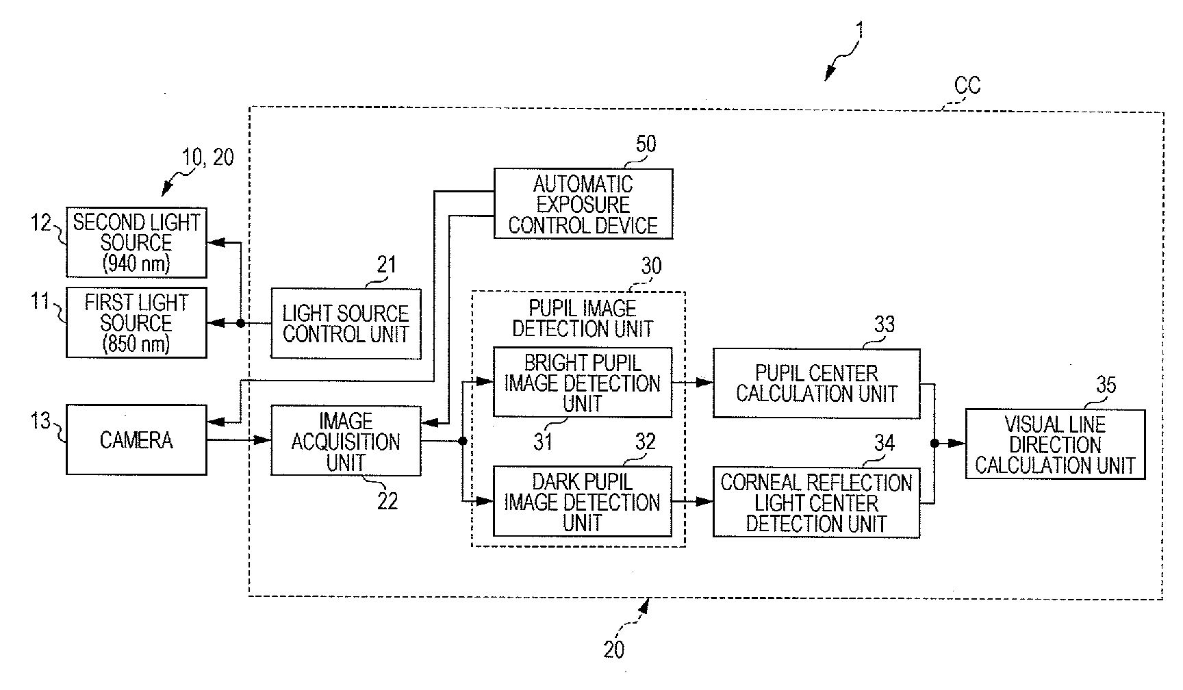
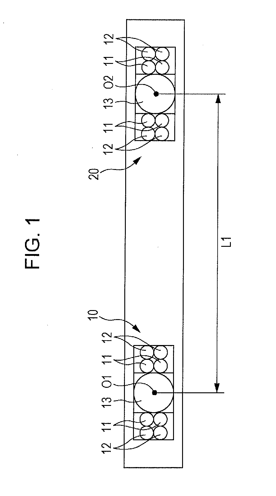
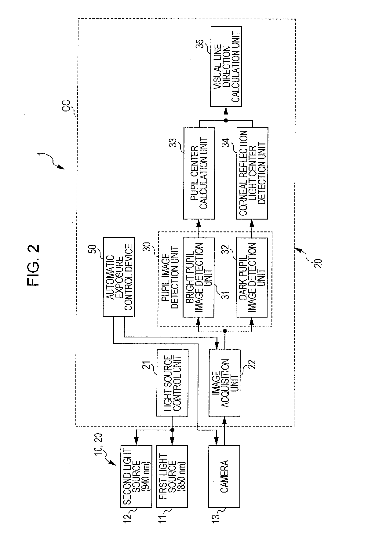
[0021]As illustrated in FIG. 2, an in-vehicle imaging device 1 of an embodiment of the present invention includes a pair of illuminating and image-capturing units 10 and 20 and a calculation control unit CC. As illustrated in FIG. 1 and FIGS. 6A and 6B, the illuminating and image-capturing unit 10 and the illuminating and image-capturing unit 20 are arranged a distance L1 away from each other. The distance L1 is set so as to be roughly equal to, for example, a distance between both eyes of a person.

[0022]The two illuminating and image-capturing units 10 and 20 each include a camera 13 and a plurality of first light sources 11 and a plurality of second light sources 12. The optical axis (the optical axis of the corresponding camera 13) of the illuminating and image-capturing unit 10 is O1, and the optical axis (the optical axis of the corresponding camera 13) of the illuminating and image-capturing unit 20 is O2. The light emission op...


PUM


Abstract

The face image of a passenger is acquired by a camera set in a vehicle cabin, the positions of a pupil and corneal reflection light of the face image are detected, and a visual line direction is calculated from the pupil and the corneal reflection light. A condition for automatic exposure control is predetermined, and the exposure time (shutter time) of the camera is controlled in accordance with the exposure condition. In a driving interval in the sunny daytime, the reference time of image luminance for the automatic exposure control is shortened, thereby enabling to follow the fluctuation of luminance inside a vehicle. In a driving interval in a cloudy condition and a driving interval in the night-time, the reference time of image luminance for the automatic exposure control is lengthened, thereby keeping automatic exposure from responding to the light of headlights of an oncoming vehicle.

Description

CLAIM OF PRIORITY[0001]This application claims benefit of priority to Japanese Patent Application No. 2014-176148 filed on Aug. 29, 2014, which is hereby incorporated by reference in its entirety.BACKGROUND[0002]1. Field of the Disclosure[0003]The present disclosure relates to an in-vehicle imaging device that is arranged inside a vehicle and acquires the image of both eyes, the image of the face, and so forth of a passenger.[0004]2. Description of the Related Art[0005]An invention relating to a pupil detection method is described in Japanese Unexamined Patent Application Publication No. 2008-246004.[0006]In this pupil detection method, a light source for giving light to both the eyes of a person and a half mirror for splitting light to be image-captured are provided, one of two split rays of light is caused to transmit through a bandpass filter for causing a wavelength of 850 nm to transmit therethrough and acquired by a first image sensor, and another split ray of light is caused ...

Claims


Application Information

Patent Timeline
IPC IPC(8): B60R1/00G06T7/00G06V10/141G06V10/143H04N5/235H04N7/18H04N9/04
CPCG06K9/00832G06T7/004H04N9/04B60R2300/8006H04N7/183H04N5/2351B60R1/00H04N5/2353G06T2207/10012G06T2207/10048G06T2207/10152G06T2207/30268G06T7/73G06V40/19G06V20/59G06V10/141G06V10/143H04N23/72H04N23/71
Inventor YASUDA, YUICHI
Owner ALPS ALPINE CO LTD
Learn More