Belt tensioner for drill press

Active Publication Date: 2016-03-10
JPW IND
View PDF8 Cites 5 Cited by
  • Summary
  • Abstract
  • Description
  • Claims
  • Application Information

AI Technical Summary

Benefits of technology

[0010]The present method and apparatus provides a drill press with a variable speed drive using a belt and pulley arrangement, and an adjustable belt tensioner on a drive belt of the belt and pulley arrangement. The adjustable belt tensioner enables the user to adjust the tension on at least one drive belt of the drill press. The u

Problems solved by technology

Power is lost in the transfer of energy from the motor to the spindle.
If some of the motor power is lost in the tr

Method used


Image

  • Belt tensioner for drill press
  • Belt tensioner for drill press
  • Belt tensioner for drill press

Examples


Example

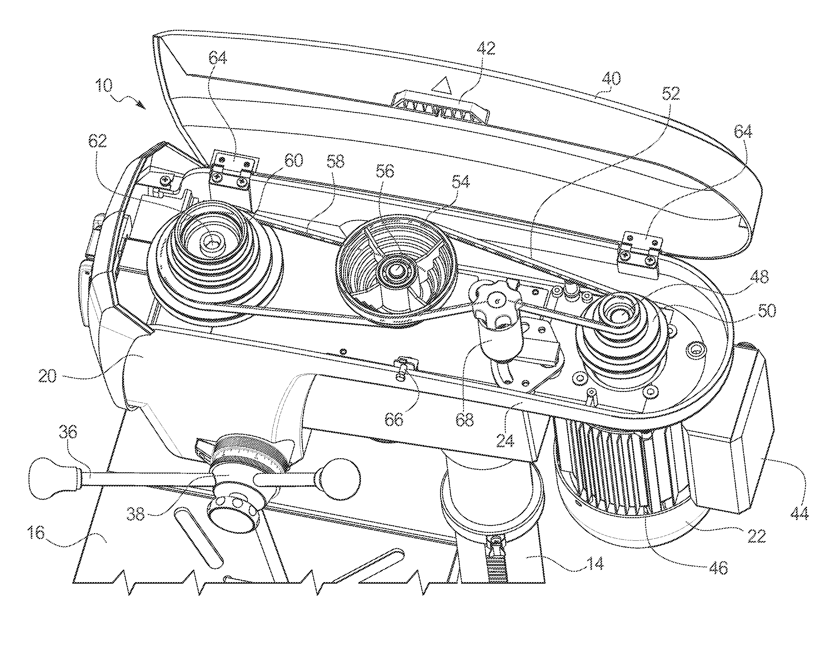
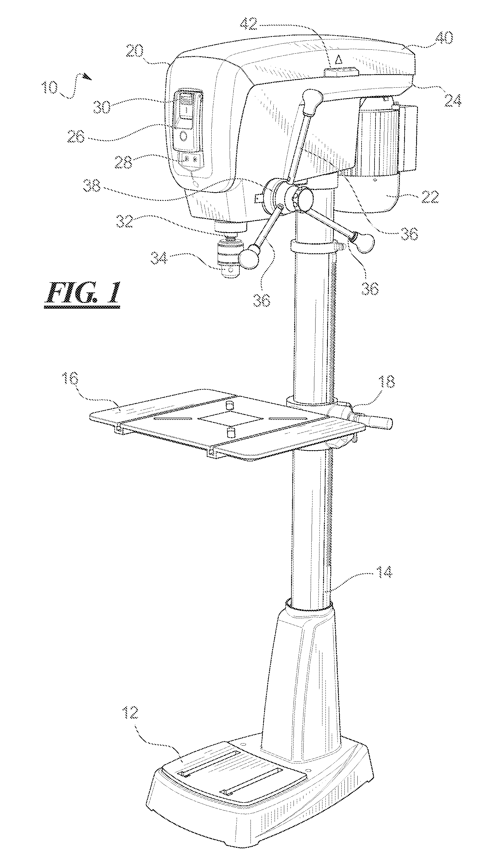
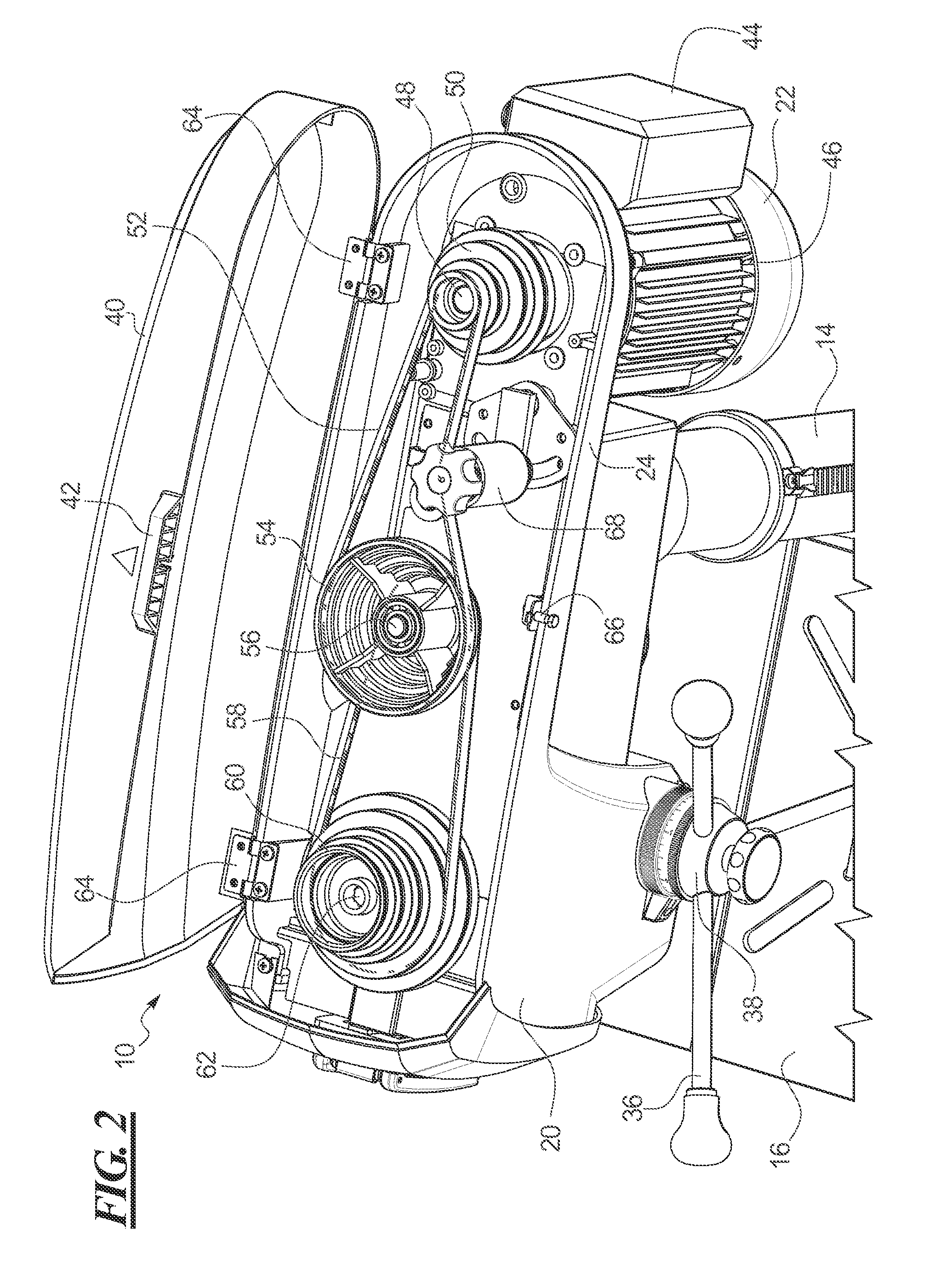
[0020]Referring first to FIG. 1, a drill press 10 includes abase 12 that may be supported on a floor or on a workbench or other surface. From the base 12 extends a column 14 that provides a vertical support for a work table 16. The table 16 may be adjusted to various positions along the column 14 and locked into preferred positions by a table lock 18. Mounted on the column 14 above the table 16 is drill press head 20 that includes a motor 22 affixed to a housing 24. The motor 22 is mounted at the back of the housing 24, while at the front of the housing 24 is a power panel 26 that includes indicators 28 to show the operating status of the drill press 10 and a power switch 30 to control the operation of the motor 22.

[0021]From the housing 24 extends a spindle 32 on which is mounted a chuck 34 for holding drill bits and other tools. The spindle 32 and chuck 34 may be raised and lowered in the head 20 by operation of a feed lever 36. Three such feed levers 36 are shown on the illustrat...


PUM

PropertyMeasurementUnit
Forceaaaaaaaaaa
Speedaaaaaaaaaa
Tensionaaaaaaaaaa

Abstract

A drill press has variable speed drive via belts on stepped pulleys that transfer rotational force from the motor to the drill press spindle. Three stepped pulleys connected by two belts are provided in the example. A belt tension roller is bears against one of the belts to provide tension for effective power transfer from the motor to the spindle. The belt tension roller is adjustable along an arcuate slot in an anchor plate and is fastenable in position by an adjustment knob on the belt tension roller. The middle pulley is mounted to vary its position so that tension adjustments on one belt by the belt tension roller result in tension adjustments on the second belt as well.

Description

CROSS-REFERENCE TO RELATED APPLICATION[0001]This application claims the benefit of U.S. Provisional Patent Application Ser. No. 62 / 047,303, filed Sep. 8, 2014, which is incorporated herein by reference.BACKGROUND OF THE INVENTION[0002]1. Field of the Invention[0003]The present invention relates generally to a power tool that may be a drib press, and more particularly to belt tensioner for use in a drill press.[0004]2. Description of the Related Art[0005]Drill presses are commonly available tools in both commercial and home workshops. A common configuration of a drill press, also known as a pedestal drill, pillar drill, or bench drill, includes a stand that supports a work table, above which is a drill head. The stand may be configured for support on the floor or on a bench or other surface. The drill head includes a number of handles, or a wheel, that is operable to control the vertical movement of a spindle and chuck for holding a drill bit or other tool. A motor in the drill head ...

Claims


Application Information

Patent Timeline
IPC IPC(8): B23Q5/14B23B39/10
CPCB23B39/10B23Q5/14B23B47/26B23Q5/10B23Q5/12F16H7/1281F16H2007/0842F16H2007/0865F16H2007/088Y10T408/67B23B47/00F16H7/12B23B39/167B23Q5/048F16H9/06
Inventor SCHWAIGER, BARRY, M.
Owner JPW IND
Why Eureka
Try Eureka