
Prefabricated foldable building module

a technology of building modules and folding parts, applied in office buildings, dwelling buildings, construction, etc., can solve the problems of inflating the cost of expensive goods, lack of skilled trades, and inability to meet the needs of construction workers, and achieves the effect of compact size and maneuverability, storage and movement with relative eas

Active Publication Date: 2016-03-10
DYNON MATTHEW
View PDF4 Cites 31 Cited by
  • Summary
  • Abstract
  • Description
  • Claims
  • Application Information

AI Technical Summary

Benefits of technology

The present invention is a modular building design that allows for flexible and versatile erection at various locations without the need for skilled labor or specialized tools. The roof and floor panels fold out within the foldable walls, making the structure more compact and easy to store and transport. The modules can be quickly deployed and collapsed after use for re-use in other locations. The design also allows for the addition of bathrooms, kitchens, and laundries in the central core, providing more flexibility for temporary or permanent use. The module can be fixed to a wheeled trailer for easy transport or stored and moved with relative ease. Overall, this invention provides a more efficient and cost-effective solution for building structures in remote or urban areas.

Problems solved by technology

An affordability problem exists for housing and other building provision in regional and remote areas where lack of skilled trades and expensive goods delivery charges inflate the cost.
However, it is often not practical, feasible or economic to transport these buildings or building elements due to their large physical size.

Method used


Image

  • Prefabricated foldable building module
  • Prefabricated foldable building module
  • Prefabricated foldable building module

Examples


Embodiment Construction

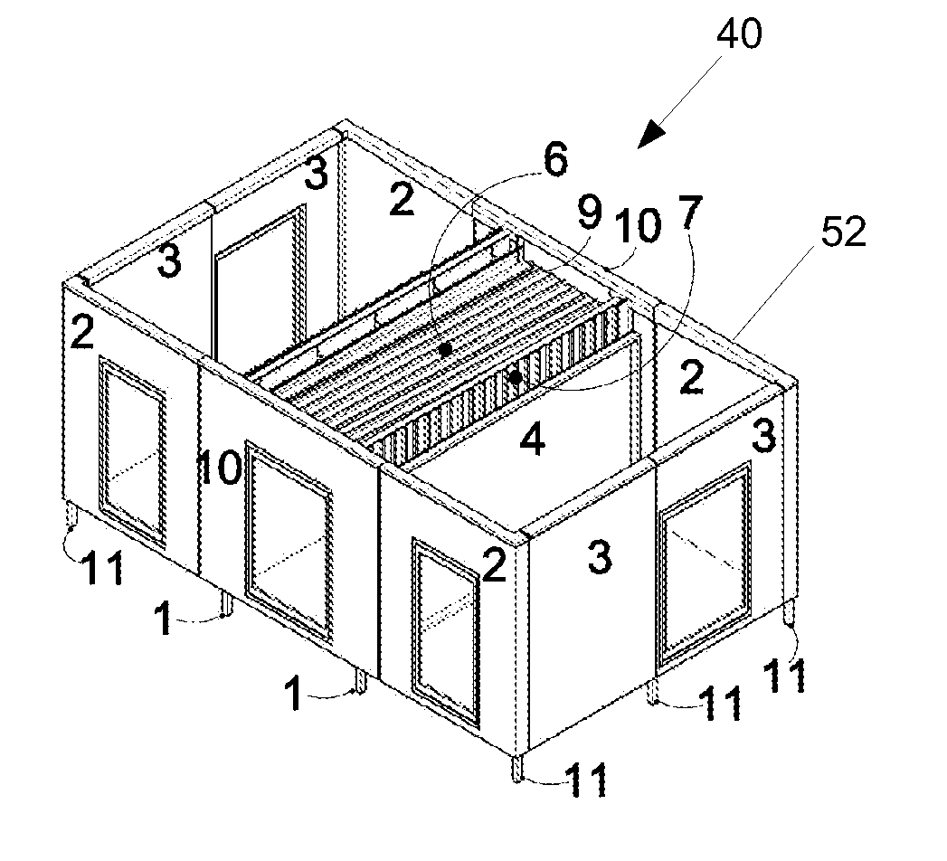
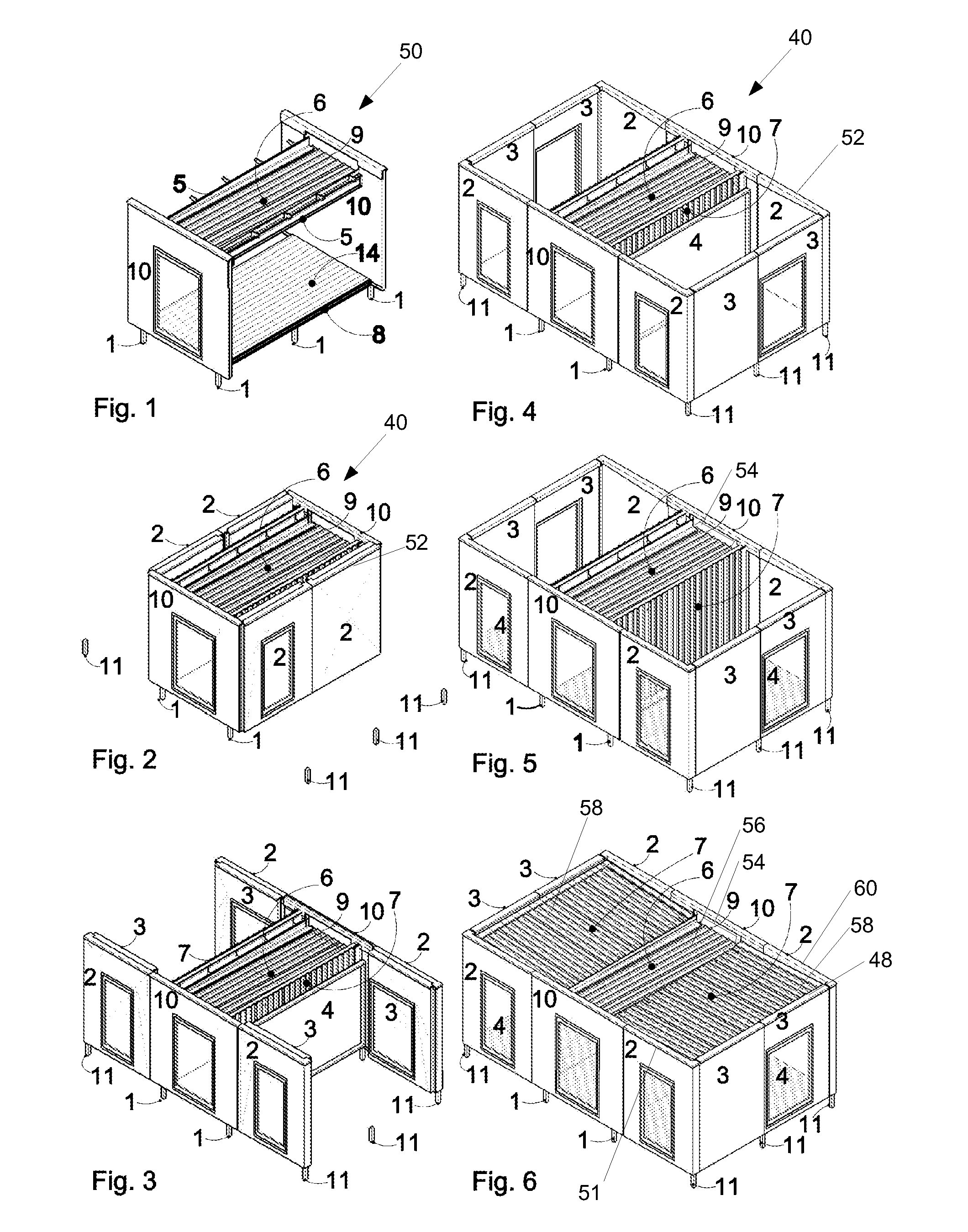
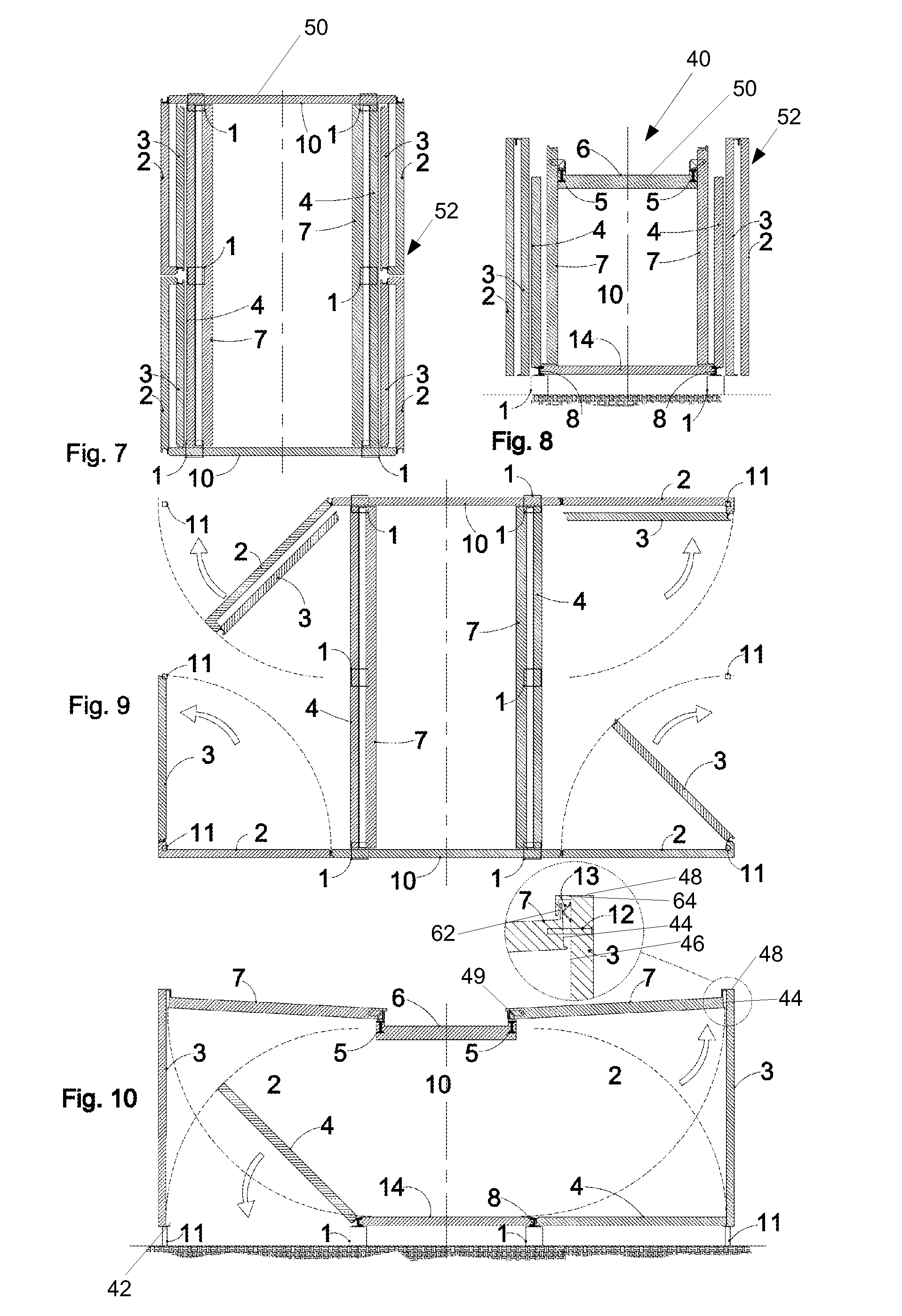
[0091]Referring to FIGS. 2-10, there is shown a standard prefabricated foldable building module 40 which is configured to expand from a first folded configuration as depicted in FIGS. 2, 7 and 8 to a second erected dwelling configuration as depicted in FIG. 6 via the intermediary steps and configurations depicted in FIGS. 3-5 and 9 and 10. Reversal of the erection steps depicted in sequential order at FIGS. 2-6 permits, after the desired length of use, contraction / collapsing of the standard prefabricated building module back to the first folded configuration of FIGS. 2, 7 and 8. The module 40 is so designed, that after re-folding it is then capable of transportation to another site, where it can be re-erected and re-used and this process may occur on multiple occasions.

[0092]The prefabricated, foldable building module 40 includes a central core 50, including a central roof portion 6, a central floor portion 14 and two opposing fixed walls 10 extending between the central roof portio...


PUM


Abstract

A prefabricated foldable building module including a central core comprising first and second opposing fixed walls with roof and floor beams interposed therebetween; a plurality of vertically foldably connected walls mounted upon the first and second walls foldable out therefrom; a pair of roof panels, each foldably connected adjacent said roof beam; a pair of floor panels each foldably connected adjacent floor beam: characterized in that the wall panels, roof panels and floor panels may be folded out from their supporting structures in a defined sequence to form an enclosed / partly enclosed building structure, and may be re-folded in reverse sequence to original configuration. Standard modules can be stretched, or joined side by side, end to end or one on top of the other to form larger buildings. The width of the central core can be increased to form an expanded central floor portion providing additional fixed area for location of bathrooms, kitchens and laundries, or for storage of unfixed furniture and building materials. Alternatively, a volumetric addition can be attached to the end of the standard module.

Description

TECHNICAL FIELD[0001]The present invention relates to prefabricated budding modules and particularly those of a hinged, fold out configuration to facilitate relatively quick deployment and erection, compact storage, efficient transport and relocation.BACKGROUND[0002]Prefabricated foldable structures already exist and provide useful accommodation for permanent occupation and also for temporary workforces involved in mining, farming, construction and re-construction in remote areas. Foldable buildings are designed to meet the requirements of efficient transport, storage and erection, retransport and reuse. Such designs fold out in a variety of different ways after arriving on site. Many however, rely on mechanical opening devices such as wheel and track systems while others require a crane to lift components into place. In most cases the roof element needs to be temporarily supported while other elements are secured in place.[0003]The demand for prefabricated structures suited for eas...

Claims


Application Information

Patent Timeline
Patent Type & Authority Applications(United States)
IPC IPC(8): E04B1/344E04B1/343E04B1/348
CPCE04B1/3442E04B1/34815E04B1/34357E04B1/34384E04B1/34336E04H1/02E04H1/06E04H1/12E04H3/08E04H3/165E04H5/02E04B1/3444E04B1/343
Inventor DYNON, MATTHEW
Owner DYNON MATTHEW
Learn More