Energy generation load compensation

a load compensation and energy generation technology, applied in the direction of dc network circuit arrangement, transportation and packaging, dc source parallel operation, etc., can solve the problems of many limitations in the technology used in developing renewable energy resources, limited success, and lack of real-time information regarding the immediate cost of energy usage. to achieve the effect of preventing over generation

Active Publication Date: 2016-03-10
HONEY BADGER INT
View PDF7 Cites 24 Cited by
  • Summary
  • Abstract
  • Description
  • Claims
  • Application Information

AI Technical Summary

Benefits of technology

[0030]The inverter energy system may include a first inverter energy string and a further inverter energy string, the method including when power is in the forward direction connecting said further inverter energy string to compensate for the usage of load from the mains power supply and when forward power or load decreases isolating said further inverter energy string to prevent over generation from the further energy string above the rate limit.

Problems solved by technology

Such programs have met with limited success for various reasons most particularly the inability of some types of energy users to curtail energy use and the lack of real-time information regarding the immediate cost of energy usage.
The technology used in developing renewable energy resources, electricity grids and current energy infrastructure suffer from many limitations.
In recent years, concerns have been raised that high demand for electricity is taxing the capacity of existing electricity generating plants.
Likewise, the electrical utility industry has for some time laboured under the problem of supplying cost effective power to comply with system peak-demand period requirements.
The problems with current domestic solar grid feed systems is that they are creating problems on the energy network regarding power quality and voltage spikes / abnormalities which requires expensive equipment to rectify it.
Furthermore domestic solar grid feed systems are reducing the amount of power that can be sold by the generators and distributors, yet the actual amount of energy produced by the generators has to remain constant due to the fluctuating nature of small scale solar energy production.
This means that the power generation companies and distributors still have the same or higher network costs, yet their income from selling and distributing the power has reduced.

Method used


Image

  • Energy generation load compensation
  • Energy generation load compensation
  • Energy generation load compensation

Examples


Embodiment Construction

[0095]The following description, given by way of example only, is described in order to provide a more precise understanding of the subject matter of a preferred embodiment or embodiments.

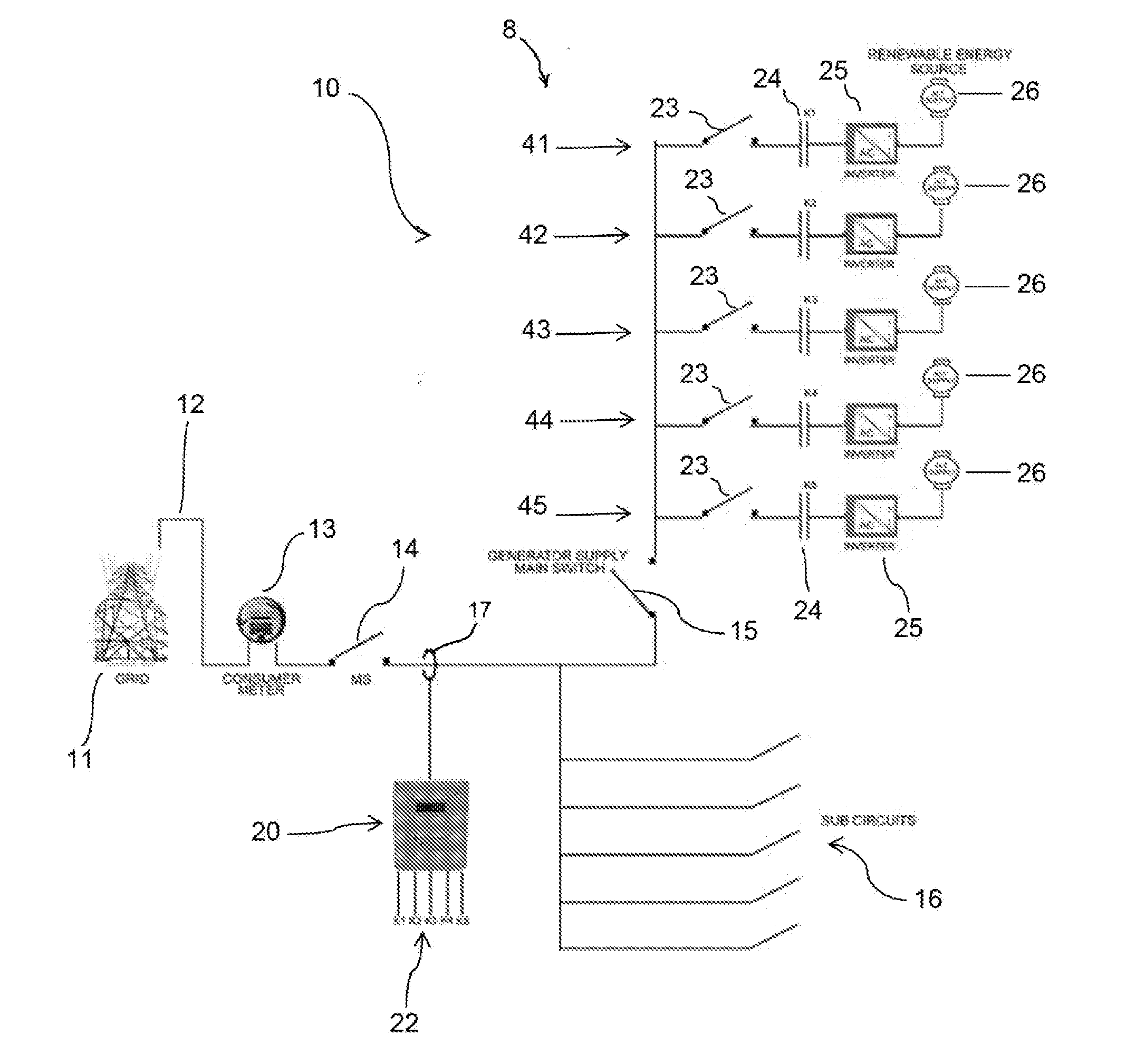
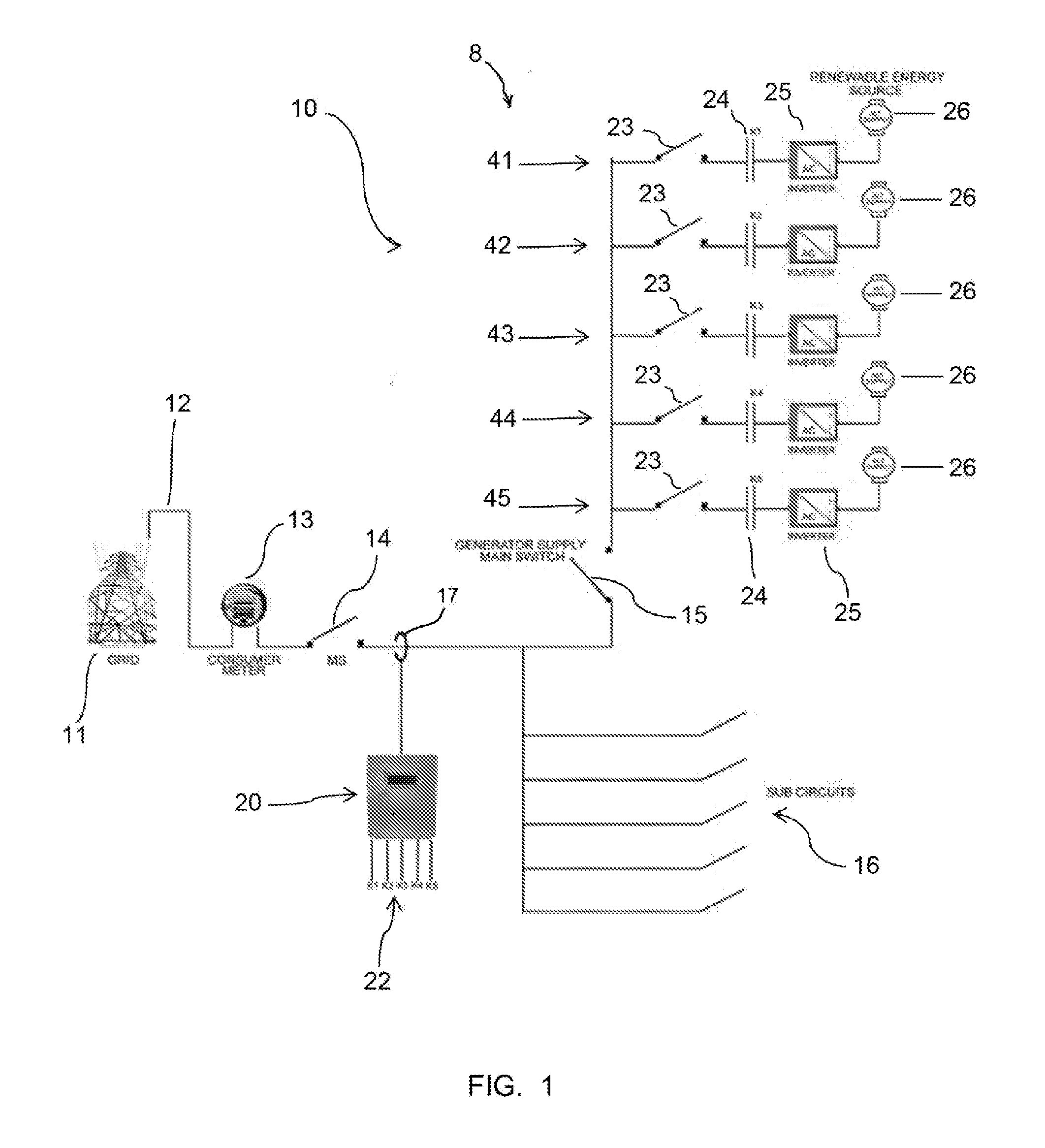
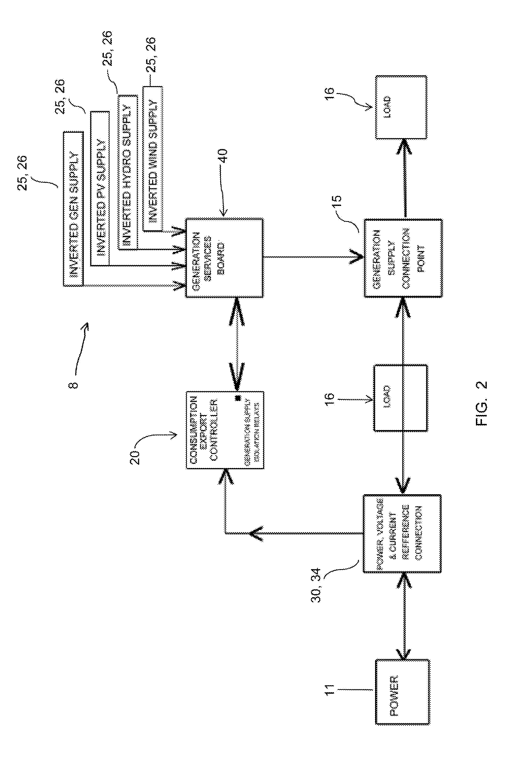
[0096]Described embodiments relate generally to methods, systems and apparatus for an energy generation load compensation and computer readable storage configured to control the performance of such methods, systems and apparatus. The energy load compensation system is typically used for Inverter Energy Systems, such as renewable energy solar photovoltaic fed grid installations, for the purpose of compensating the load from the mains supply grid and the described embodiments are particularly suited to such purposes. Embodiments are not, however, limited to such use. For example, the Inverter Energy System at site may be an array of photovoltaic panels and inverter(s) as discussed, wind turbine(s) and inverter(s), hydroelectric turbine(s) and inverter(s), or any other energy source and inverter combi...


PUM


Abstract

An inverter energy system supplies power to a site. The inverter energy system comprises a number of solar strings, each solar string including a solar panel(s) as a renewable energy source and an inverter. The inverter energy system is connected to a mains power supply (grid) and to a site load (sub circuits). The forward or reverse power flow into or out of the mains power supply is monitored at a monitoring point at the site. A rate limit is set for power flow into and / or or out of the mains power supply. The supply of power from the inverter energy system is controlled so that the power flow into or out of the mains power supply is within the set rate limit.

Description

FIELD OF THE INVENTION[0001]This invention relates in general to renewable energy generation within a utility grid. In particular, the present invention relates to a system, method and apparatus for renewable energy generation for the purpose of compensating the load from the utility grid and providing a network protection device which incorporates isolation from the utility grid and the renewable energy system.BACKGROUND OF THE INVENTION[0002]It should be noted that reference to the prior art herein is not to be taken as an acknowledgement that such prior art constitutes common general knowledge in the art.[0003]Electricity or power is an essential part of modern life. In residences, in businesses, in institutions and in other locations, consumers use electricity in a variety of ways. Utilities deliver power generated by power plants through a network of transmission and distribution lines. This network is hereinafter referred to as the “power transmission and distribution grid,”“t...

Claims


Application Information

Patent Timeline
Patent Type & Authority Applications(United States)
IPC IPC(8): H02J3/38
CPCH02J3/383G01R21/133H02J2300/24H02J3/381Y02E10/56H02J3/466H02J3/38
Inventor ROGERS, GREGORY, NEVILLE
Owner HONEY BADGER INT
Why Eureka
Try Eureka