
Hood for ultrasonic endoscope and ultrasonic endoscope

a technology of ultrasonic endoscopy and hood, which is applied in the field of hoods for ultrasonic endoscopy and ultrasonic endoscopy devices, can solve the problems of loss of visibility from observation windows, inability to obtain image inside tissue, and reflected ultrasonic waves at the gap

Active Publication Date: 2016-03-17
FUJIFILM CORP
View PDF9 Cites 4 Cited by
  • Summary
  • Abstract
  • Description
  • Claims
  • Application Information

AI Technical Summary

Benefits of technology

The invention prevents the ultrasonic transducer from getting close to the body wall when it is brought into close contact with the body wall. This is done by using an eaves-shaped part between the observation window and the body wall, ensuring that the visual range of the observation window is not hindered. This reduces the hindrance on the visual range of the observation window and allows for reliable observation of the treatment instrument even when the hood body is used. Additionally, the invention prevents the hood body from getting attached to the distal end part of the endoscope without hindering the visual range of the observation window.

Problems solved by technology

Incidentally, when there is a gap between an ultrasonic transducer and a body wall, an ultrasonic wave is reflected at the gap and an image inside a tissue cannot be obtained.
At this time, visibility from an observation window may be lost because the body wall also gets into close contact with an outer surface of the observation window.
If visibility from the observation window is lost, a puncturing point (pricking point) cannot be visually recognized.
In addition, confirmation of the puncturing point can be also done by using an ultrasonic image without using an optical image, but even in that case, there is a problem of giving an unpleasant impression because the image will be a reddish uncanny image in whole if the body wall gets into close contact with the observation window.
Even in the case of using the hood described in the Japanese Patent Application Laid-Open No. 2009-268751, the hood cannot prevent the body wall from getting into close contact with the observation window, because the object region and the ultrasonic transducer are brought into close contact with each other by sucking the object region into the hood.

Method used


Image

  • Hood for ultrasonic endoscope and ultrasonic endoscope
  • Hood for ultrasonic endoscope and ultrasonic endoscope
  • Hood for ultrasonic endoscope and ultrasonic endoscope

Examples


first embodiment

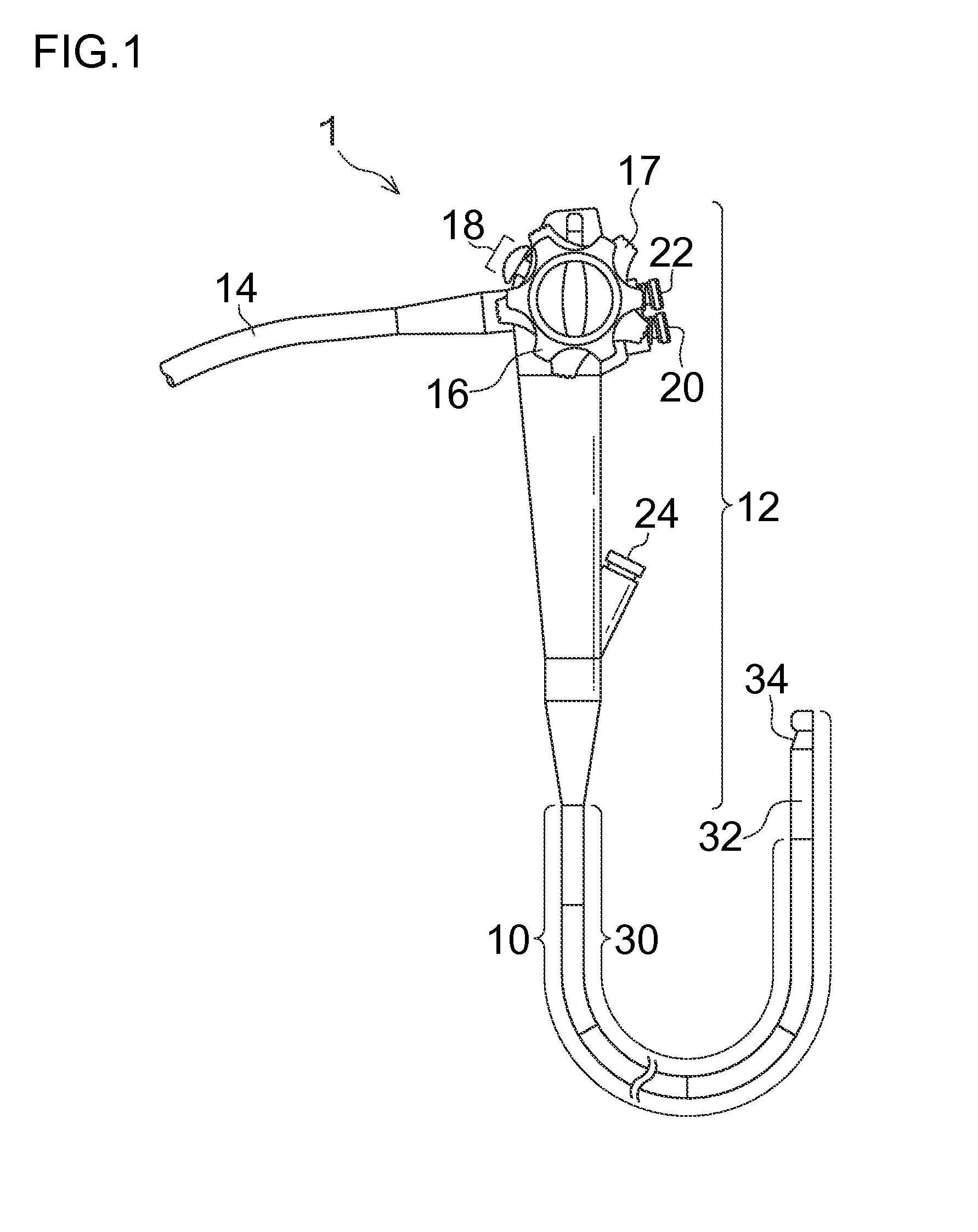
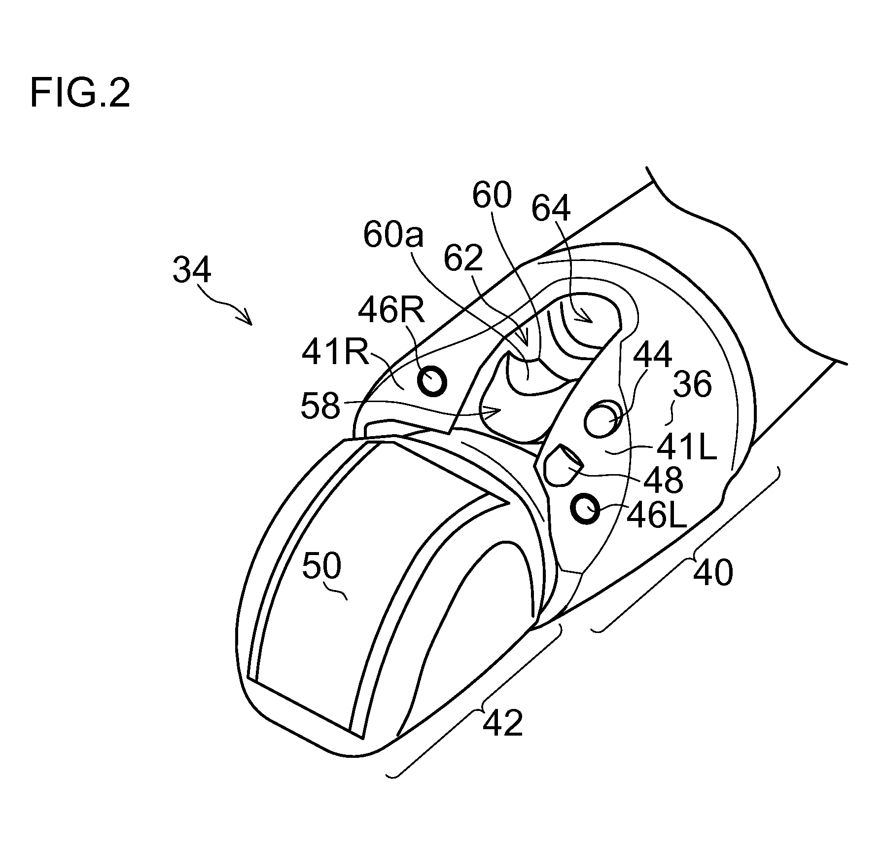
[0075]FIG. 3 illustrates the distal end part 34 of the endoscope 1 and a hood for an ultrasonic endoscope 100 (hereinafter simply called a hood 100) in a first embodiment, and is a perspective view illustrating a state where the hood 100 is detached from the distal end part 34. FIG. 4 is a perspective view illustrating a state where the hood 100 is attached to the distal end part 34.

[0076]The hood 100 illustrated in these figures includes: a hood body 102 which is formed in a cylindrical shape by a frame member and an elastic material such as, for example, silicone rubber or fluorocarbon rubber; and a notch 108 extending from a distal end to a proximal end side. However, the hood 100 may be not necessarily transparent.

[0077]An inner circumference surface of the hood body 102 has approximately the same diameter as the cylindrical outer circumference surface 36 of the distal end part 34, the hood body 102 fits onto the outer circumference surface 36 of the distal end part 34 as in FIG...

second embodiment

[0086]Next, a hood for an ultrasonic endoscope 150 (hereinafter simply called a hood 150) in a second embodiment will be explained.

[0087]FIG. 8 is a perspective view illustrating the hood 150 in the second embodiment. Additionally, the same part as or a similar function part to the hood 100 in the first embodiment is given the same reference numeral and its explanation will be omitted.

[0088]As illustrated in the figure, in the hood 150 in the second embodiment, at least the eaves-shaped part 106 is composed of a frame member 152, and the frame member 152 at the eaves-shaped part 106 protrudes toward in front of the observation window 44 in a state of the hood 150 (hood body 102) being attached to the distal end part 34.

[0089]According to the hood 150 in the second embodiment, in the same manner as the hood 100 in the first embodiment, when the ultrasonic transmitting and receiving plane of the ultrasonic transducer 50 is brought into close contact with a body wall, the frame member ...

third embodiment

[0091]Next, a hood for an ultrasonic endoscope 200 (hereinafter simply called a hood 200) in a third embodiment will be explained.

[0092]FIG. 10 is a perspective view illustrating the hood 200 in the third embodiment. Additionally, the same part as or a similar function part to the hood 100 in the first embodiment is given the same reference numeral and its explanation will be omitted.

[0093]As illustrated in the figure, in the hood 200 in the third embodiment, the eaves-shaped part 106 is given a habit (reformed) into a state where the eaves-shaped part 106 deforms toward a radially outside relative to an axis of the hood body 102.

[0094]On the other hand, as a switching device, one end of a string member 202 is coupled with the inner circumference surface or the like of the eaves-shaped part 106, and the other end of the string member 202 is led out from, for example, the treatment instrument introduction port 24 of the operation part 12 via the treatment instrument insertion channel...


PUM


Abstract

The present invention provides a hood for an ultrasonic endoscope and an ultrasonic endoscope that prevent a body wall from getting into close contact with an observation window at a time such as when an ultrasonic transducer is brought into close contact with the body wall. In a hood for an ultrasonic endoscope to be attached to the ultrasonic endoscope, a notch is formed at a front edge of the hood, and a front edge corner at an observation window side along the notch is provided as an eaves-shaped part. The eaves-shaped part protrudes in front of the observation window, and when an ultrasonic transducer is brought into close contact with the body wall, the eaves-shaped part lies between the body wall and the observation window, thereby preventing the body wall from getting into close contact with the observation window.

Description

CROSS-REFERENCE TO RELATED APPLICATIONS[0001]The patent application claims priority under 35 U.S.C. §119 to Japanese Patent Application No. 2014-187816, filed on Sep. 16, 2014. Each of the above application(s) is hereby expressly incorporated by reference, in its entirety, into the present application.BACKGROUND OF THE INVENTION[0002]1. Field of the Invention[0003]The present invention relates to a hood for an ultrasonic endoscope and an ultrasonic endoscope device, and in particular, to a hood for an ultrasonic endoscope and an ultrasonic endoscope that prevent close contact of a body wall (such as a mucous membrane) to an observation window.[0004]2. Description of the Related Art[0005]As an ultrasonic endoscope, a known one is equipped with an electronic scanning ultrasonic transducer at a distal end part of an insertion part of an endoscope. While an ultrasonic image of a lesion is being obtained by the ultrasonic transducer, some treatment is performed, such as a puncture needle...

Claims


Application Information

Patent Timeline
IPC IPC(8): A61B1/00A61B1/018A61B8/12
CPCA61B1/00089A61B1/018A61B8/12A61B1/00082A61B8/4272A61B8/445A61B8/44A61B8/4444A61B8/4455
Inventor MORIMOTO, YASUHIKO
Owner FUJIFILM CORP
Learn More