
Transport container having an identification carrier

a technology of identification carrier and transport container, which is applied in the field of transport containers, can solve the problems of affecting the readability of cards, the envelope of the hermetically sealed hollow chamber may open, and the negative effect, etc., and achieves the effects of improving the conventional transport container, cost-effective, and easy to read

Inactive Publication Date: 2016-03-17
PAUL CRAEMER
View PDF2 Cites 10 Cited by
  • Summary
  • Abstract
  • Description
  • Claims
  • Application Information

AI Technical Summary

Benefits of technology

The invention is a way to make a transport container smarter and more cost-effective. It involves adding an electronic wireless identification carrier to the container. This carrier has a chip and an antenna and is embedded in a protective casing. This makes it easy to read even when the container is filled with water or has high water content. The invention also allows for easy replacement or retrofitting of containers with identification carriers, as well as cleaning the containers to high standards. Overall, this makes the transport container safer, more secure, and more efficient.

Problems solved by technology

This double-wall section of the transport container does not serve to create a hermetically sealed hollow chamber, for the purpose of holding the identification carrier.
Such hollow chambers have the disadvantage that, if the container wall becomes deformed, the hermetically sealed envelope of the hollow chamber may open up, for example, along welded seams.
This allows water to seep into the hollow chamber, which can have a negative impact on the readability of the card.
Furthermore, such undesirable and unforeseen cracks can have a negative effect hygienically on the transport container, because such hollow chambers, which are now accessible to bacteria and other contaminants, cannot be adequately cleaned.

Method used


Image

  • Transport container having an identification carrier
  • Transport container having an identification carrier
  • Transport container having an identification carrier

Examples


Embodiment Construction

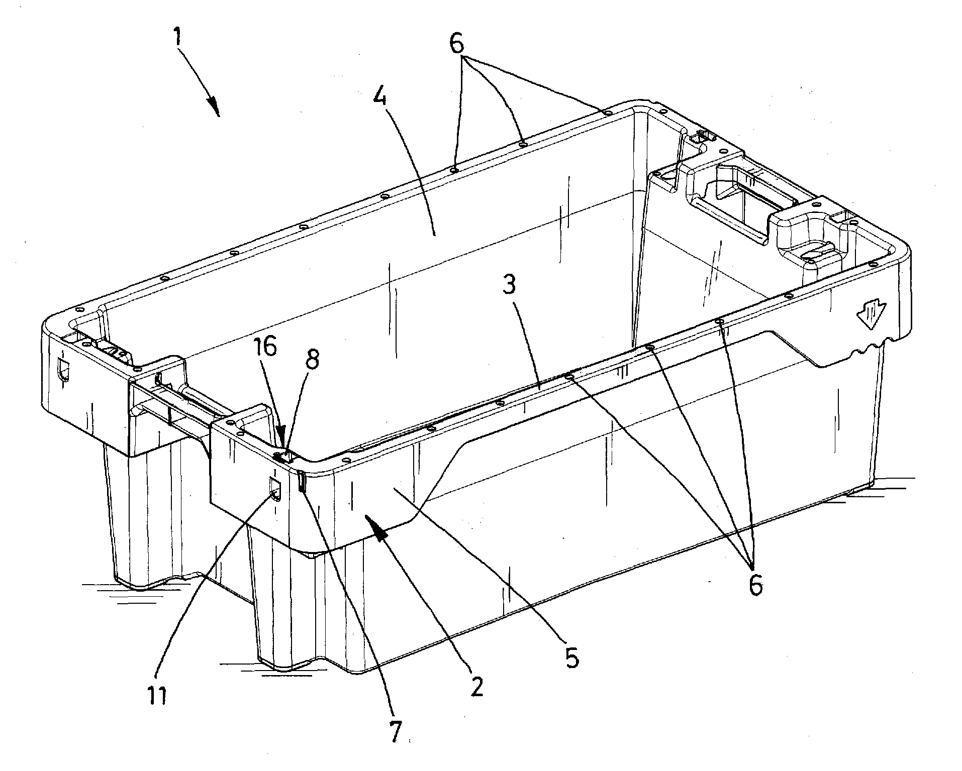
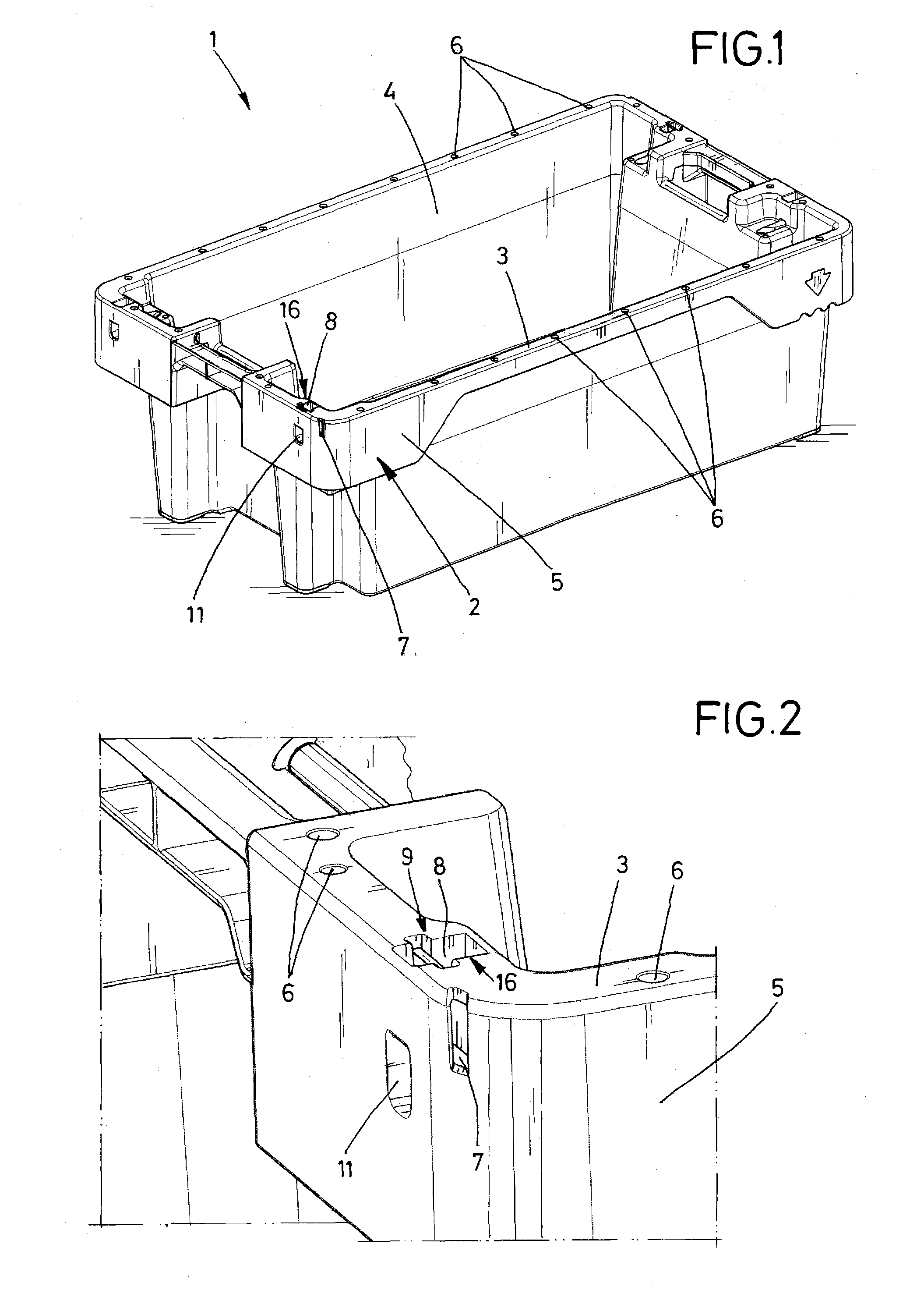
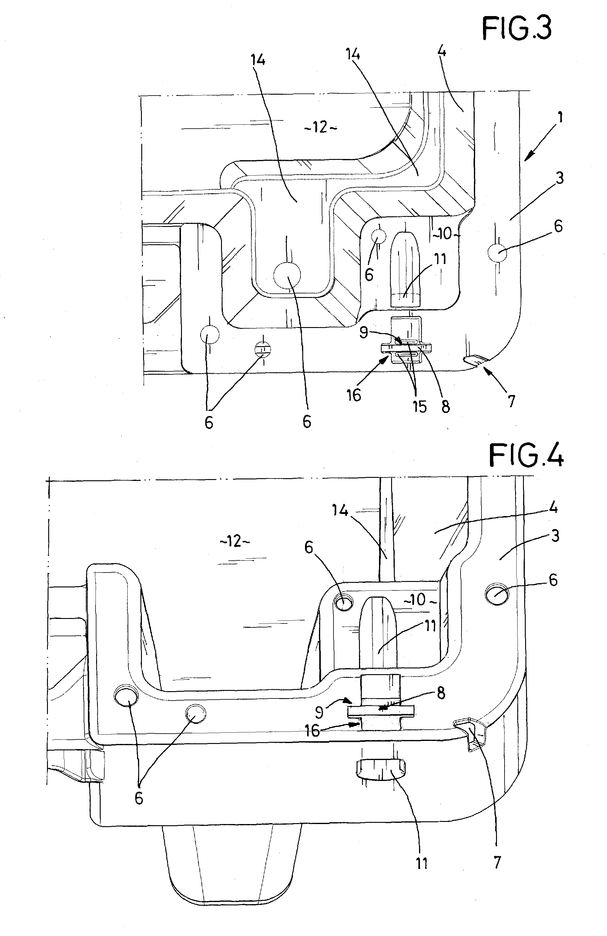
[0033]A transport container 1, which is embodied as a fish crate, is shown in the drawings. The transport container 1 has a double-wall section 2 that is constructed as an upper circumferential collar on the transport container 1. The wall section 2 is closed at the top by a horizontally oriented connector web 3, which connects an inner wall 4 and an outer wall 5 of the double-wall section 2 with each other. A plurality of drain holes 6 are provided in the connector web 3, through which rinse water can flow when the transport container 1, placed upside down, is rinsed with water. When being cleaned in this manner, the water also flows into the double-wall section 2. The inner wall 4 extends beyond the double-wall section 2 downward and forms the side walls of the transport container 1 and also forms as a single integral component the floor of the transport container 1.

[0034]The double-wall section 2 has an insertion slot 7, through which a smart card 8 is inserted into the double-wa...


PUM


Abstract

A transport container having a receptacle for holding an electronic, wireless identification device in the form of a smart card. The transport container has a double-walled wall section formed by an inner wall and an outer all. The receptacle is defined by guides and ribs and an insertion slot is provided in the outer wall via which the card is inserted into the receptacle. The insertion slot is offset to the receptacle, so that the smart card or elements of the receptacle must be elastically deformable to insert the card into the receptacle. The ribs and guides ensure that the card is reliably held in the receptacle. The ribs also ensure that the card is held at least 1.5 mm away from the inner and outer walls, thereby preventing buildup of a moisture film on the smart card, to avoid impairment of the ability to read the card.

Description

BACKGROUND INFORMATION[0001]1. Field of the Invention[0002]The invention relates to the field of transport containers and particularly, to such container for food chilled with ice.[0003]2. Discussion of the Prior Art[0004]The electronic wireless identification carriers have advantages over adhesive labels, because they enable machine identification of the transport container. If the transport container serves as a fish crate, for example, to hold freshly caught fish and ice, the identification carrier serves to identify the specific fish crate, which has probably already been sold online while the fishing vessel is still at sea. The ability to readily and accurately read off the information on these identification carriers is therefore of significant importance in the subsequent handling and transport of the fish crate.[0005]Particularly when used as a fish crate, attaching the identification carrier entails considerable requirements: On the one hand, a certain minimum distance to w...

Claims


Application Information

Patent Timeline
IPC IPC(8): B65D25/20B65D21/02B65D85/00
CPCB65D25/205B65D85/70B65D21/0209B65D21/045B65D2203/10
Inventor FINKE, RALF-PETERSCHAEFER, HUBERT
Owner PAUL CRAEMER
Learn More