Vibration resistant flex flange ball stud

a ball stud and flex flange technology, which is applied in the direction of pivots, shafts and bearings, couplings, etc., can solve the problems of loss of high material embedding, and high embedding in bolted joints, so as to reduce the loss of preload, and improve the overall minimum clamp load

Active Publication Date: 2016-03-17
BORGWARNER INC
View PDF1 Cites 5 Cited by
  • Summary
  • Abstract
  • Description
  • Claims
  • Application Information

AI Technical Summary

Benefits of technology

[0012]This disclosure relates to a flex flange ball stud that is relatively short but has customizable stiffness by adjusting the flange to be springier as desired. Spring rates can be tailored by the design, thickness and size of the flexible flange. The flexible flange can essentially change the spring rate of the ball stud, emulating a longer fastener. Longer fasteners tolerate force loading deviations with longer fatigue life, lower preload loss (more effective clamp-loading) and lower material embedding.
[0013]It is desirable for bolted joint applications to have an effective spring rate due to thermal expansion variation with high temperatures in turbocharger applications, high vibration, and applied loading.
[0014]A ball stud design may include a ball section with a hex head extending above a flexible flange. A shaft is adjacent to the flexible flange with a preferred narrower threaded shaft portion extending farther opposite the ball end. The flange allows subtle flex for thermal expansion.
[0015]The flex flange ball stud allows for thermal expansion variation, high vibration applied loading, and effective spring K (stiffness) management, which is critical for short grip lengths associated with turbocharger bolted joints. It lowers embedding and eliminates loss of preload. As such, a flex flange ball stud is vibration resistant and more tolerant of loads.
[0016]The flex flange ball stud may eliminate additional components, such as nuts. While the design may be used with an nut, a nut may be eliminated if the design is used with tapered hole applications. Besides nuts, locking threads and mechanical capture features can be eliminated as prevention of self-loosening of the ball stud is less important when using the flex flange ball stud. This results in lowered cost and improved ease of assembly.
[0017]The flex flange ball stud allows for drop-in replacement and can be easily integrated into existing turbocharger applications.

Problems solved by technology

Standard ball studs with short grip lengths result in stiff fasteners, i.e. short bolts and joints, which result in high material embedding.
High turbocharger temperatures (cause material creep), few fasteners for a load (cause more stress per fastener), and limited flange head fasteners (cause high stress) can all cause high embedding in bolted joints.
High embedding of bolted joints contributes to lowering of fastener preload, which can result in loss of overall minimum clamp load, less effective bolted joints, and joint failure, especially for multi-plate applications.

Method used


Image

  • Vibration resistant flex flange ball stud
  • Vibration resistant flex flange ball stud
  • Vibration resistant flex flange ball stud

Examples


Embodiment Construction

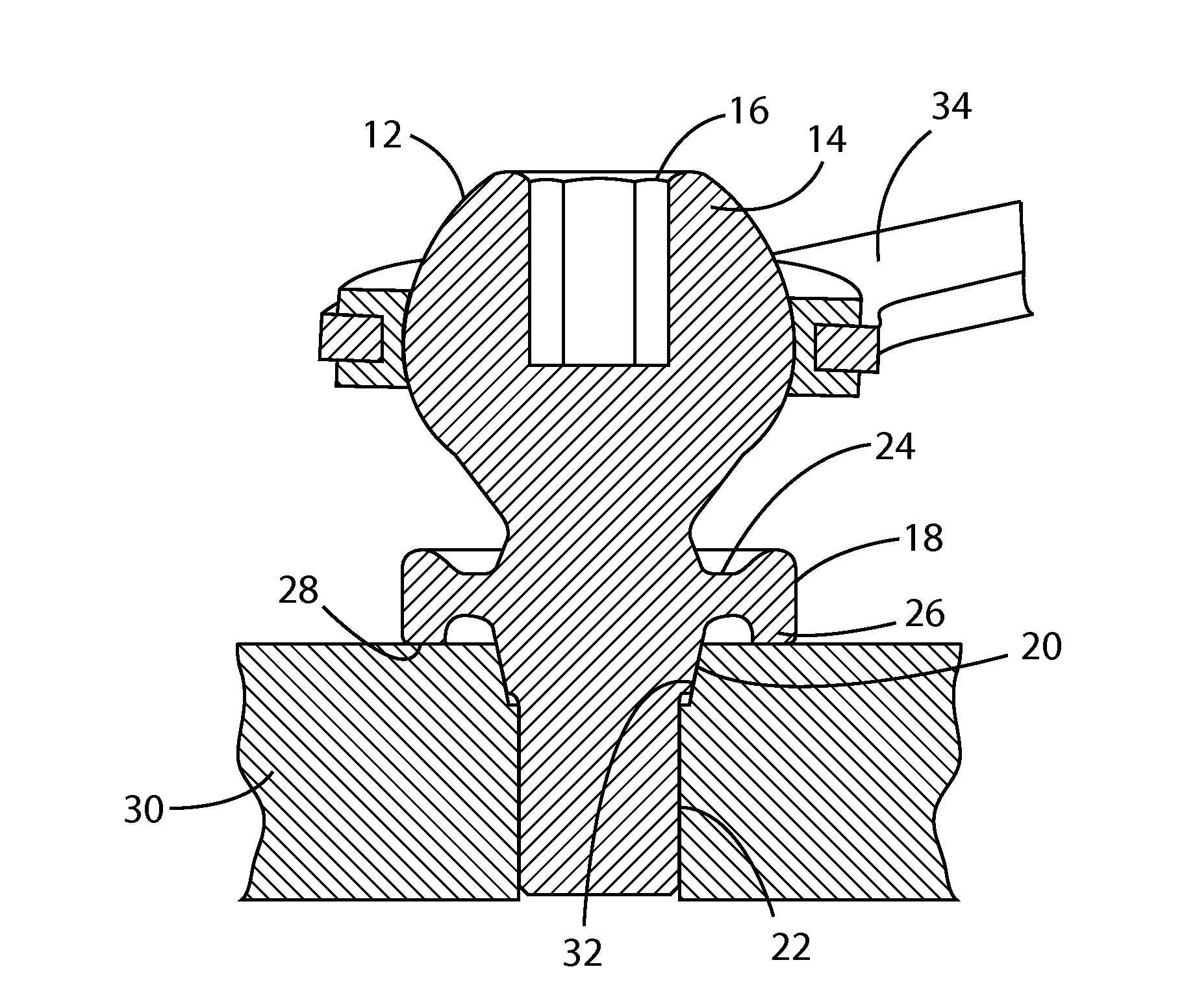
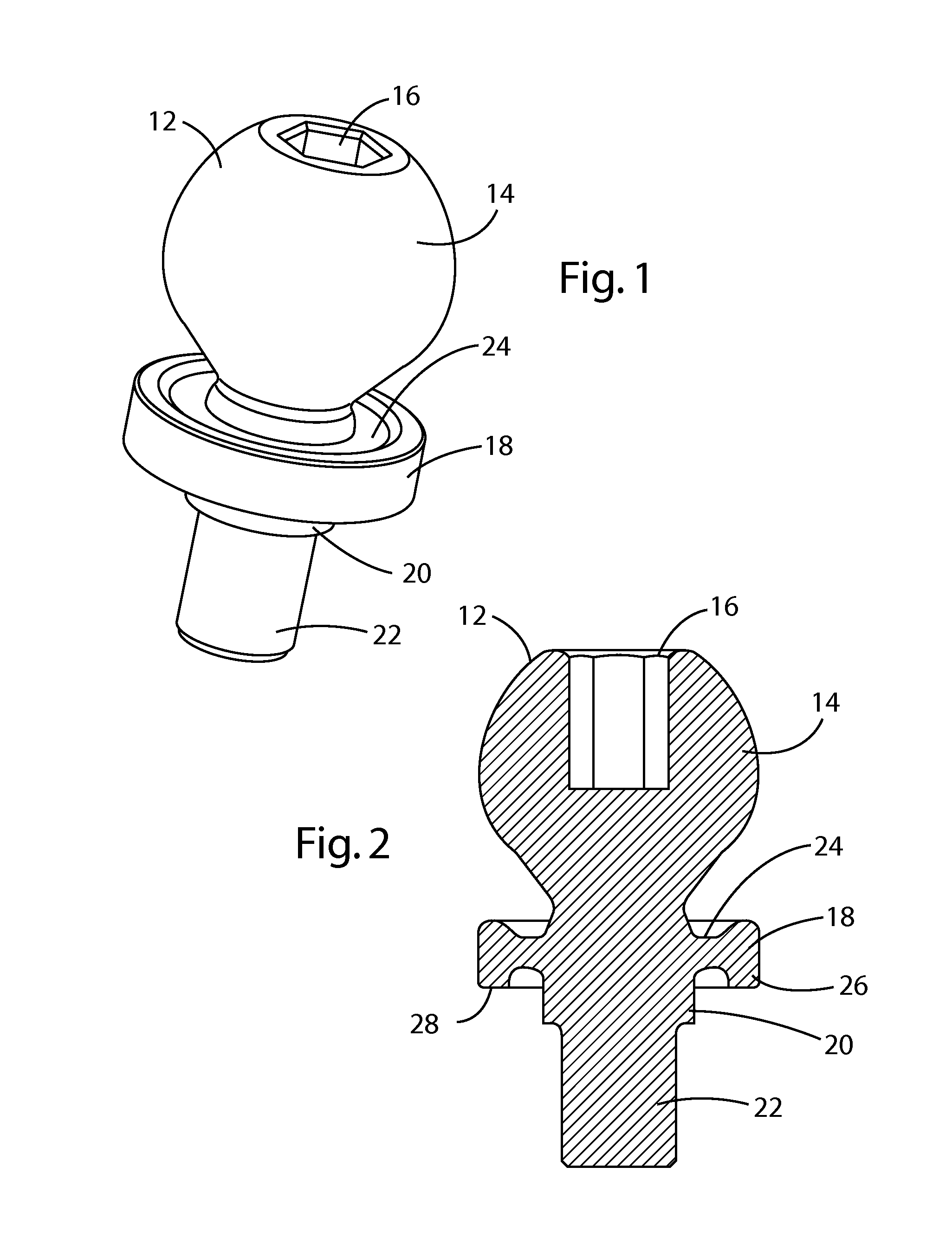
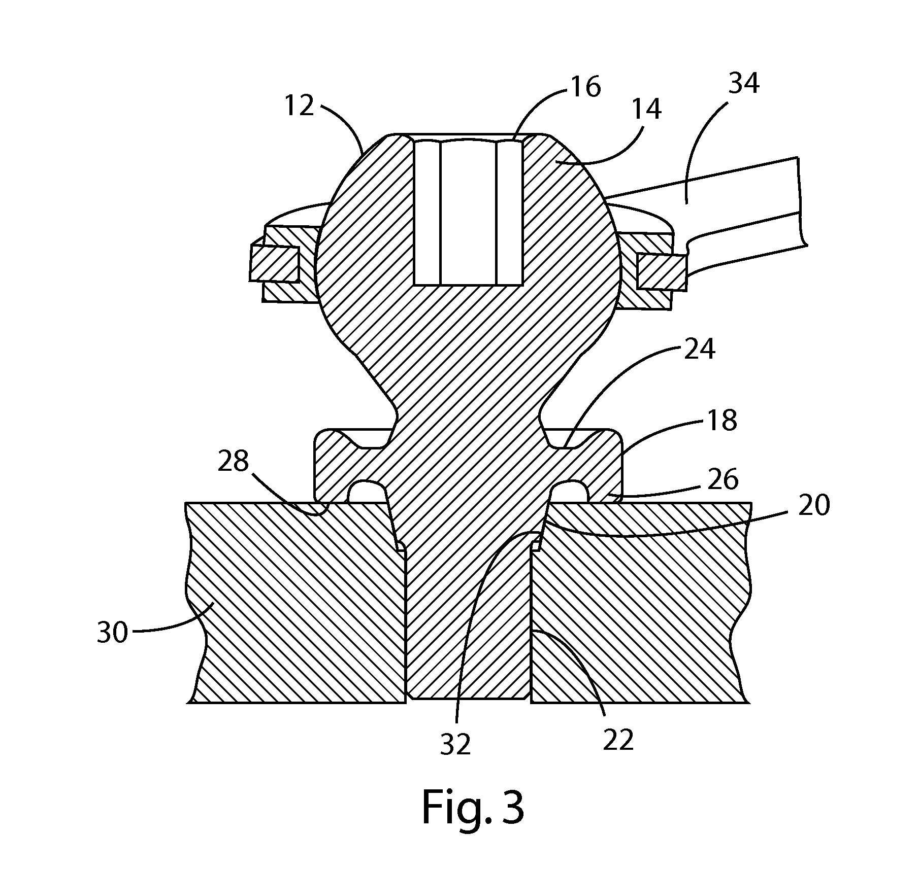
[0023]A turbocharger is generally known and includes a turbine and a compressor, wherein a compressor impeller is rotatably driven via a rotatable shaft by a turbine wheel. The turbocharger often uses ball studs in linkage applications. Short grip lengths are often associated with turbocharger bolted joints.

[0024]Referring to FIGS. 1 through 4, a ball stud 12 may include a ball section 14 with a hex head 16 extending above a flexible flange 18. The flexible flange 18 extends from a center of the ball stud 12. A first shaft portion 20 extending opposite the ball section 14 is preferably adjacent to the flexible flange 18 with a narrower threaded shaft portion 22 extending further from the ball section 14. The flexible flange 18 allows subtle flex for thermal expansion and essentially changes the spring rate of the ball stud 12 to emulate a longer fastener.

[0025]The flexible flange 18 preferably has a narrow circumference 24 closest to the center of the ball stud 12 with a distal circ...


PUM


Abstract

A ball stud (12) with a relatively short grip length, adapted for use with a turbocharger, having a flexible flange (18) extending from a center of the ball stud (12). The flexible flange (18) is between a ball section (14) and a first shaft portion (20) adjacent to the flexible flange (18) and preferably a narrower threaded shaft portion (22) extending further from the ball section (14). The first shaft portion (20) may be tapered to fit in a complementary aperture (32) of a plate (30). The flexible flange (18) preferably includes a narrow circumference (24) adjacent to a center of the ball stud (12) with a circumferential lip (26) adapted to engage a plate (30). The flexible flange (18) allows subtle flex for thermal expansion and essentially changes a spring rate of the ball stud (12) to emulate a longer fastener.

Description

CROSS-REFERENCE TO RELATED APPLICATION[0001]This application claims priority to and all benefits of U.S. Provisional Application 61 / 813,749, filed on Apr. 19, 2013, entitled “Flex Flange Vibration Resistant Ball Stud”.BACKGROUND[0002]1. Field of the Disclosure[0003]This disclosure relates to a ball stud with a flex flange. More particularly, this disclosure relates to a ball stud with a relatively short grip length having a flex flange between a ball end and a shaft end that essentially changes the spring rate of the ball stud to emulate a longer fastener.[0004]2. Description of Related Art[0005]Advantages of turbocharging include increased power output, lower fuel consumption and reduced pollutant emissions. The turbocharging of engines is no longer primarily seen from a high-power performance perspective, but is rather viewed as a means of reducing fuel consumption and environmental pollution on account of lower carbon dioxide (CO2) emissions. Currently, a primary reason for turbo...

Claims


Application Information

Patent Timeline
Patent Type & Authority Applications(United States)
IPC IPC(8): F16C11/06F16C11/08
CPCF16C11/08F16C11/0604
Inventor BUCKING, MICHAEL
Owner BORGWARNER INC
Why Eureka
Try Eureka