Method of simulating formation of lithography features by self-assembly of block copolymers

Inactive Publication Date: 2016-03-17
ASML NETHERLANDS BV
View PDF2 Cites 1 Cited by
  • Summary
  • Abstract
  • Description
  • Claims
  • Application Information

AI Technical Summary

Benefits of technology

[0028]It is an object of the invention to, for example, o

Problems solved by technology

Instead, the resolution is mainly limited to the pattern density on the imprint template.
When applied in a thin film, geometric confinement may pose

Method used


Image

  • Method of simulating formation of lithography features by self-assembly of block copolymers
  • Method of simulating formation of lithography features by self-assembly of block copolymers
  • Method of simulating formation of lithography features by self-assembly of block copolymers

Examples


Example

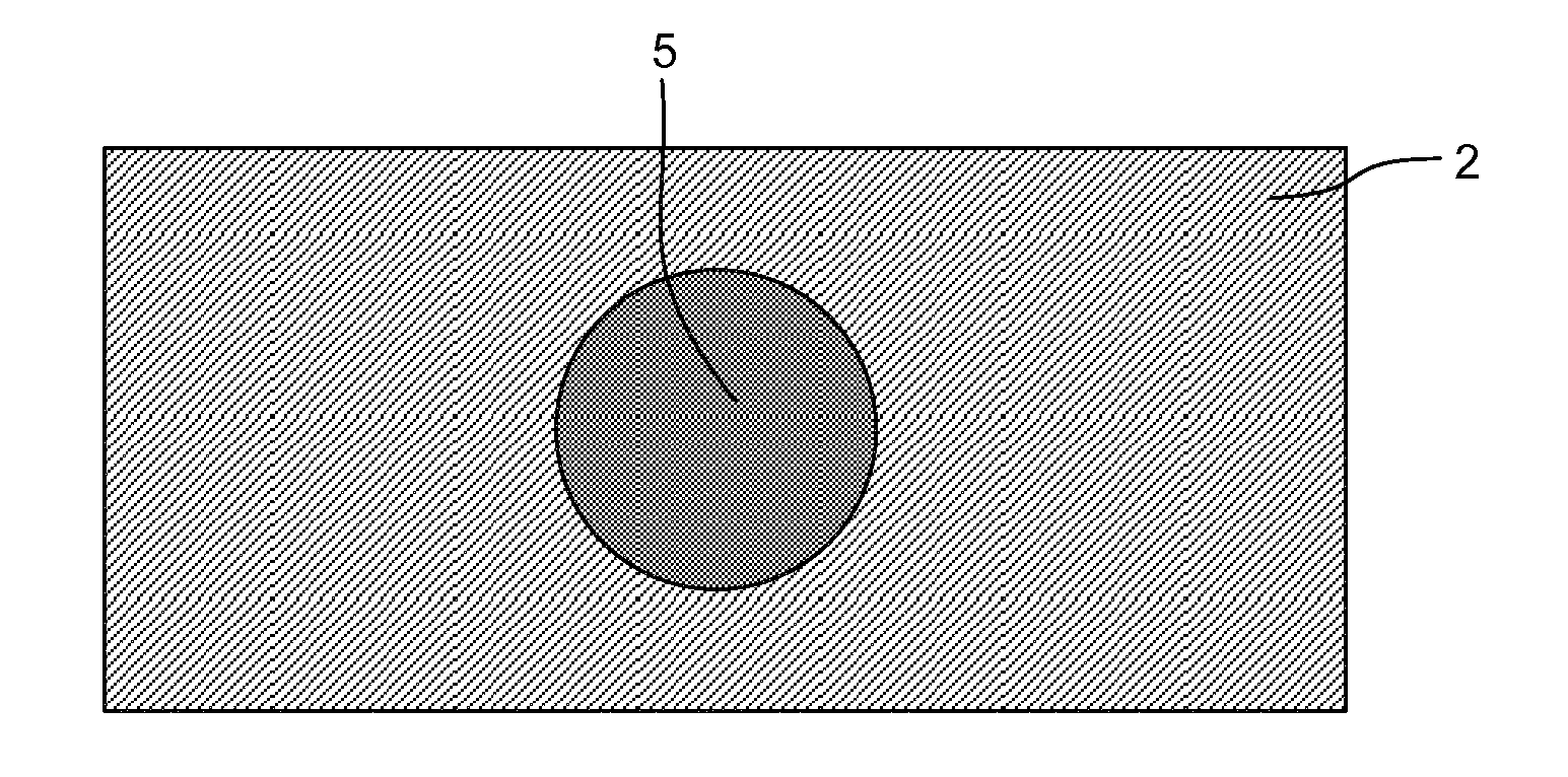
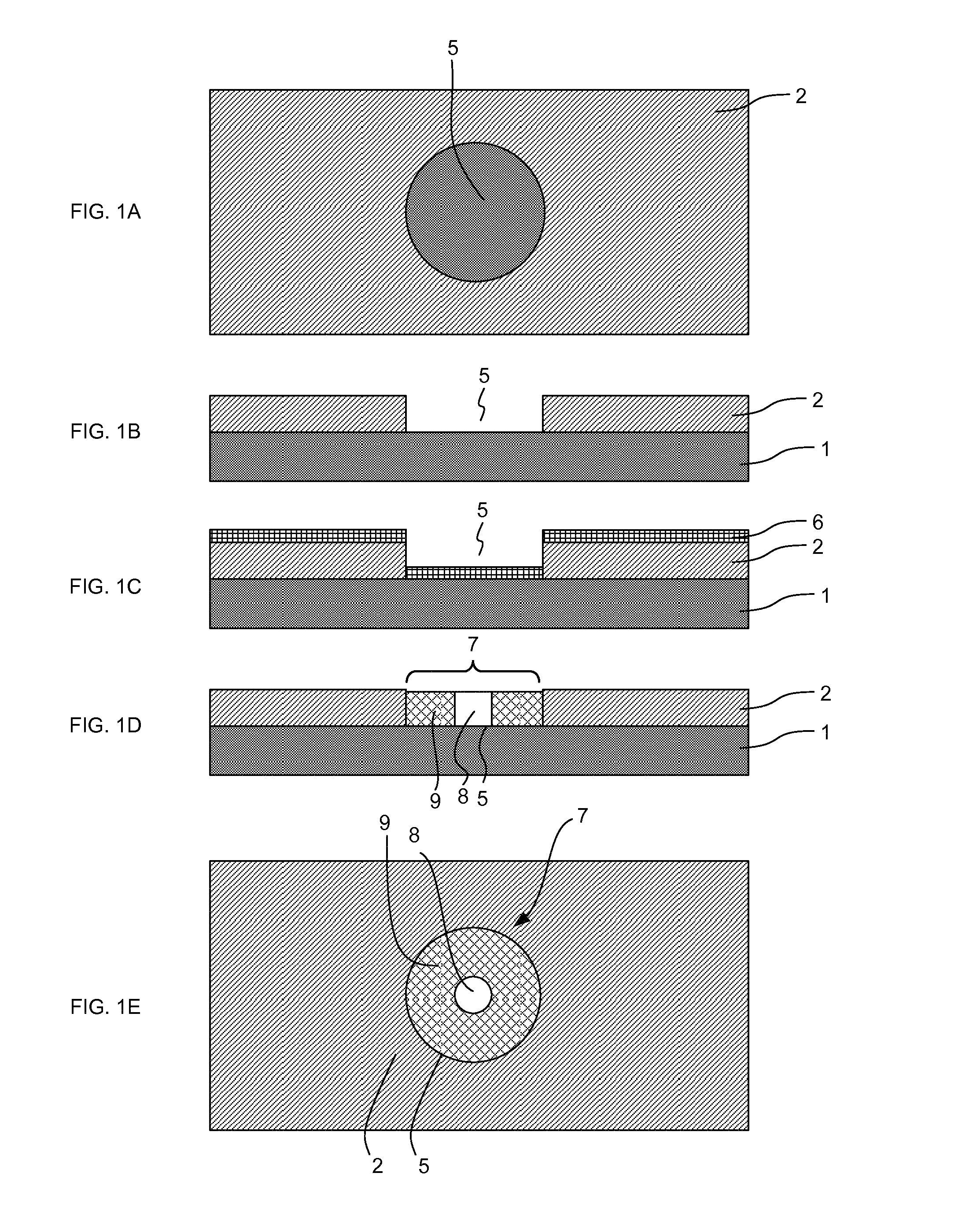
[0065]FIGS. 1A and 1B show, in plan view and cross-section respectively, part of a substrate 1 to which a lithography process using self-assembly of BCP is applied. An anti-reflection coating may be present on the surface of the substrate 1. The anti-reflection coating (if present) may be an organic material, such as, for example, ARC 29, from Brewer Science Inc. of Rolla, Mo. The anti-reflection coating may be an inorganic material such as, for example, SiC or SiON. A neutral layer may be provided on the anti-reflection coating. A layer of resist 2 is applied to the substrate 1. The layer of resist 2 may, for example, be a photo-resist. The layer of resist 2 is patterned with a contact hole resist recess 5. The contact hole resist recess 5 may be formed by photolithography, imprint lithography or another lithographic process.

[0066]In FIG. 1C, a BCP layer 6 has been deposited onto the substrate 1 and the resist 2. The BCP layer 6 is shown with a uniform thickness within the resist r...


PUM


Abstract

A method of determining an uncertainty in the position of a domain within a self-assembly block copolymer (BCP) feature. The method includes simulating a BCP feature, calculating a minimum energy position of a first domain within the simulated BCP feature, simulating the application of a potential that causes the position of the first domain to be displaced from the minimum energy position, simulating release of the potential back toward the minimum energy, recording a plurality of energies of the BCP feature during the release and recording at each of the plurality of energies a displacement of the first domain from the minimum energy position, calculating, from the recorded energies and recorded displacements, a probability distribution indicating a probability of the first domain being displaced from the minimum energy position, and, from the probability distribution, calculating an uncertainty in the position of the first domain within the BCP feature.

Description

CROSS-REFERENCE TO RELATED APPLICATIONS[0001]This application claims the benefit of U.S. provisional application 61 / 829,118, which was filed on May 30, 2013 and which is incorporated herein in its entirety by reference.FIELD[0002]The present invention relates to a method of simulating formation of lithography features by self-assembly of block copolymer. The method may be used to determine an uncertainty in the position of a feature formed using block copolymer.BACKGROUND[0003]In lithography for device manufacture, there is an ongoing desire to reduce the size of features in a lithographic pattern in order to increase the density of features on a given substrate area. Patterns of smaller features having critical dimensions (CD) at nano-scale allow for greater concentrations of device or circuit structures, yielding potential improvements in size reduction and manufacturing costs for electronic and other devices. In projection photolithography, the push for smaller features has resul...

Claims


Application Information

Patent Timeline
IPC IPC(8): G06F17/50
CPCG06F17/5081G06F17/5009G03F7/0002G06F30/20G06F30/398G06F2119/18
Inventor WUISTER, SANDER FREDERIKDRUZHININA, TAMARAVAN MALE, JANKLEIN-WOLTERINK, JOANNEAMBESI, DAVIDE
Owner ASML NETHERLANDS BV
Why Eureka
Try Eureka