

Thermal management system for smc inductors
- Summary
- Abstract
- Description
- Claims
- Application Information
AI Technical Summary
Benefits of technology
Problems solved by technology
Method used
Image

Examples
embodiment one
with Reference to FIG. 1
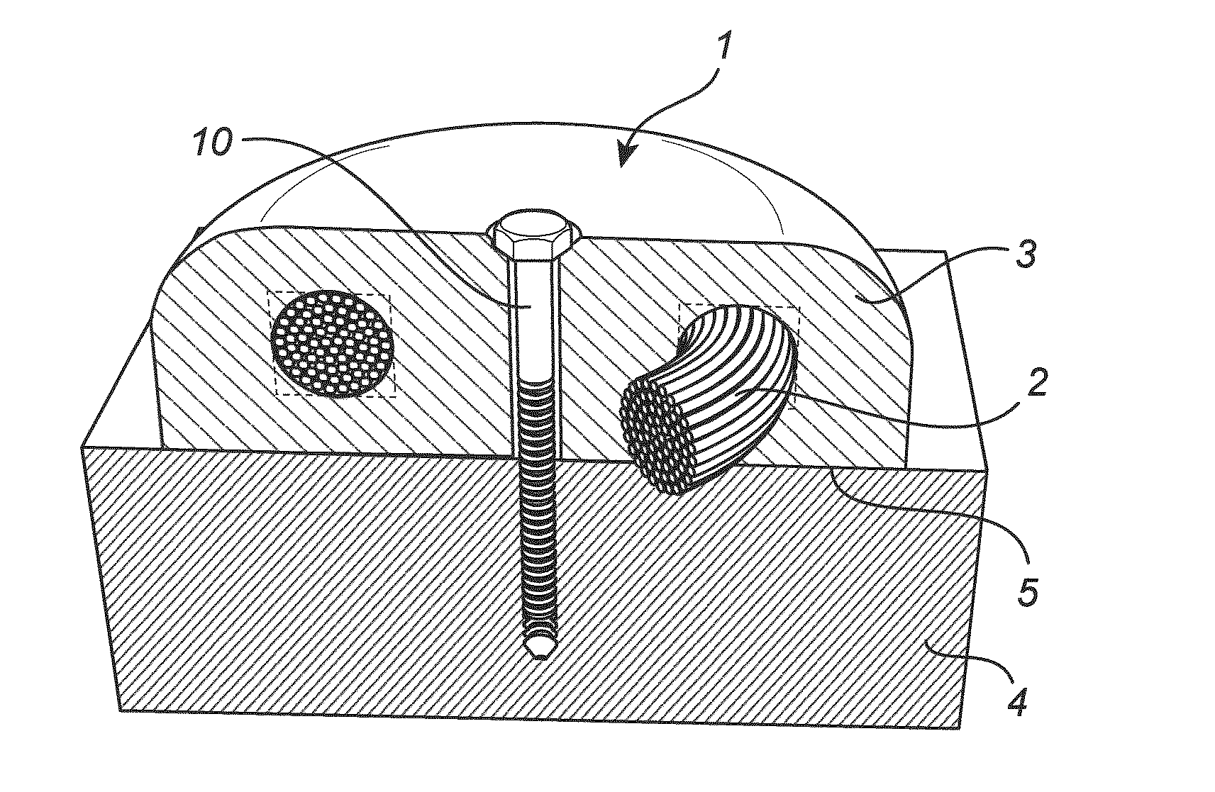
[0053]When the energy content reaches a certain point it becomes problematic to create inductive components with integrated coils due to over-heating of the conducting wire leading to drastically decreased efficiency, decreased life time of the insulation materials or insulation material breakdown.
[0054]In such cases, the present invention includes the first embodiment of using a soft magnetic mouldable material, embedding the annularly wound coil 2 completely in the core 3 material which has thermal conductivity above 1.5 W / m*K more preferable above 2 W / m*K, most preferable above 3 W / m*K, creating a direct thermal coupling between the coil and core material, the core material acting as a thermal conductor conducting heat from said coil 2. The first embodiment further includes adjusting the shape of the bottom surface area 5 of the soft magnetic mouldable material, increasing the core's surface into a circular shape so it can have thermal contact with larger ...
embodiment two
with Reference to FIG. 2& FIG. 3
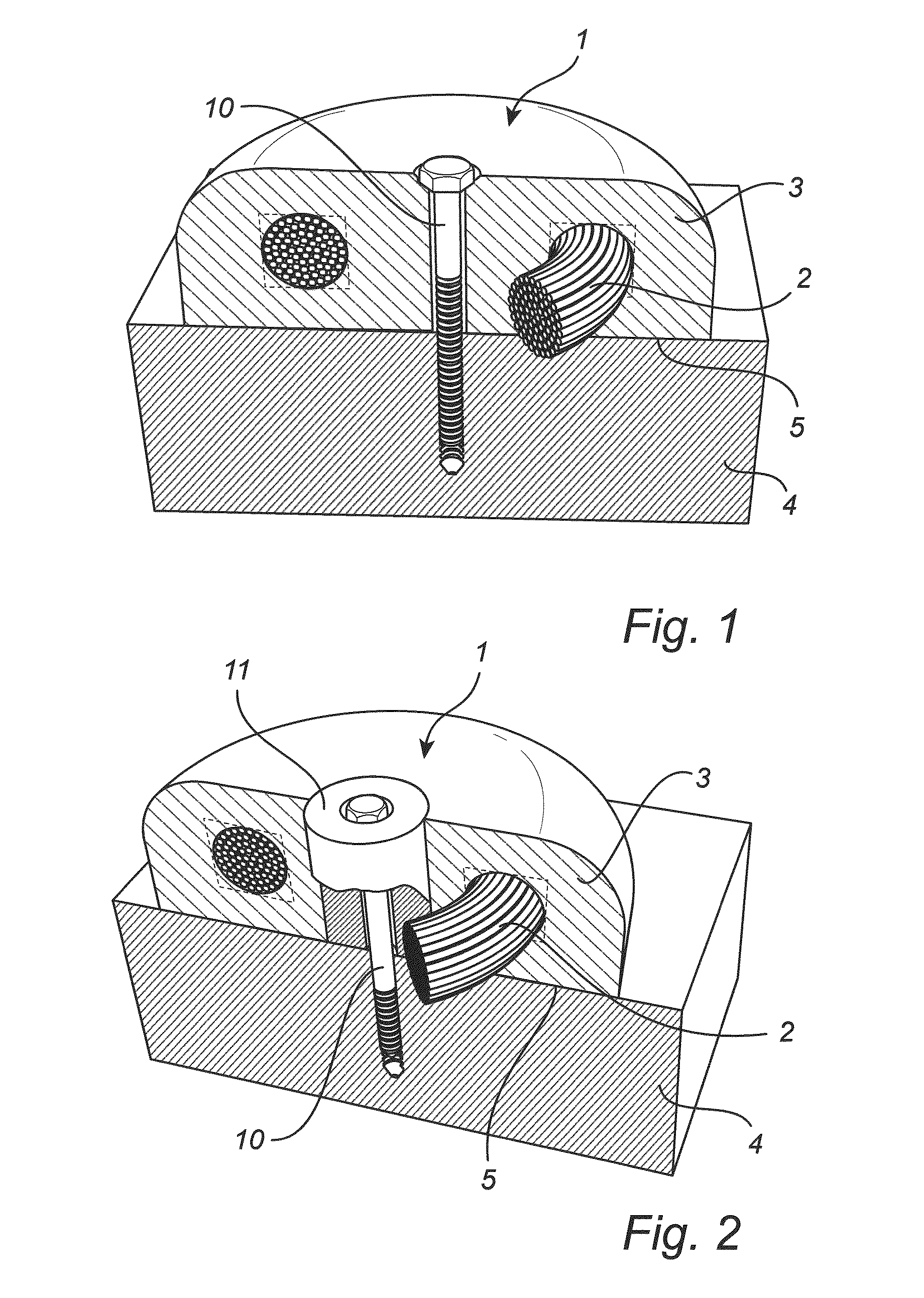
[0057]This invention also includes a second embodiment which leads to even more efficient cooling properties, enabling the design of inductor units 1 with even higher energy content and / or, depending on technical requirements, higher efficiency of the inductor. All elements previously described in embodiment one are applicable for this second embodiment.
[0058]The second embodiment further includes the integration or moulding of a highly thermally conductive thermally connecting fixture 11, which does not cause, or causes negligible, induction heating effects. This could be either a non-magnetic material or a magnetic material with low electrical conductivity. The integration or moulding of a heat conductor into the core 3 material substantially enhances the heat transferring capacity compared to using only the SMC core material. This can be realized by placing a centrum highly thermally conductive rod 11, acting as a thermally connecting fixture, in t...
embodiment three
with Reference to FIG. 4& FIG. 5
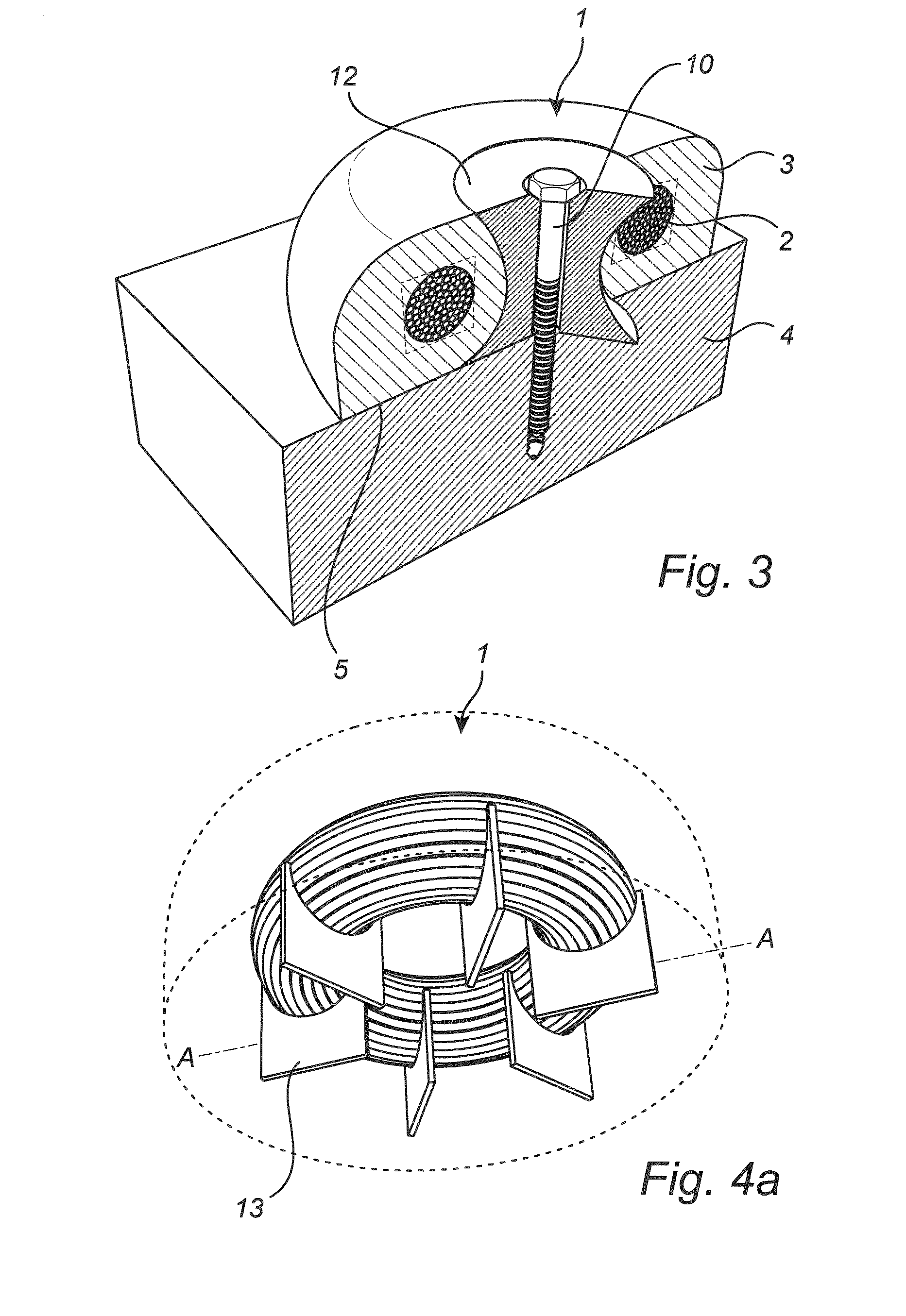
[0060]This invention also includes a third embodiment which leads to even more efficient cooling properties, enabling the design of inductor units with even higher energy content and / or, depending on technical requirements, higher efficiency of the inductor. All elements previously described in embodiment one are applicable for this third embodiment.
[0061]This third embodiment further includes the integration or moulding of one or more thermal connecting fixtures 13-17 to be placed directly against the coil 2 at certain points in the inductor (see FIGS. 4a, 4b, 5a-5c). These thermal connecting fixtures can be made with any, non-magnetic, highly thermally conductive material, as explained in embodiment two, having substantially better thermal conductivity than the SMC based core materials, preferably aluminum or aluminum oxide. This will substantially enhance the heat transferring capacity of the inductor 1 compared to using only SMC materials or soft ...
PUM
 Abstract
Description
Claims
Application Information