Size-separation of dry granular materials
- Summary
- Abstract
- Description
- Claims
- Application Information
AI Technical Summary
Benefits of technology
Problems solved by technology
Method used
Image

Examples
first embodiment
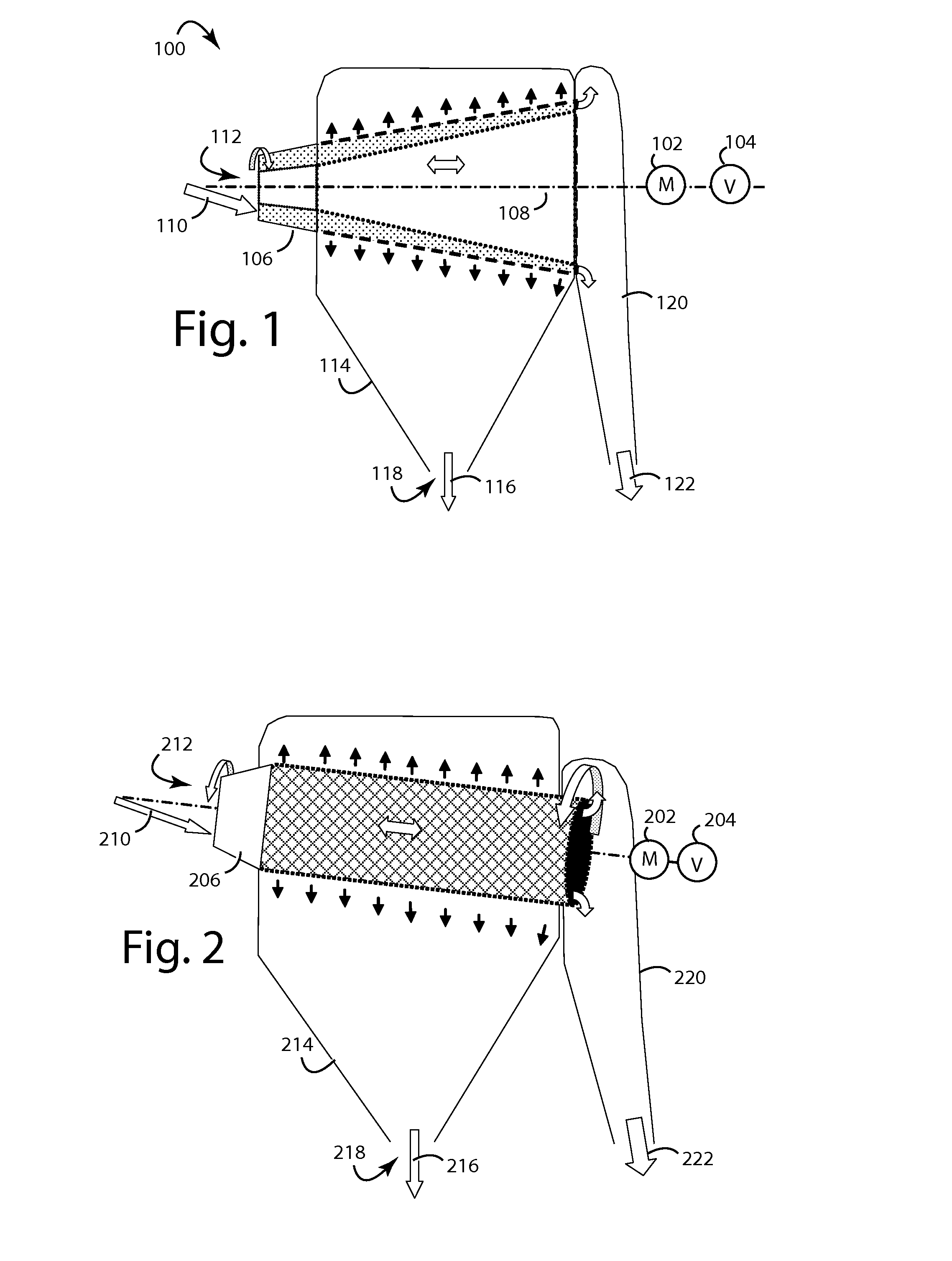
[0033]FIG. 1 represents the present invention, a conical sieve system 100. A speed-controlled motor (M) 102 and a vibrator (V) 104 are attached to spin and vibrate a conical screen 106 that rotates on an axis 108. A dry mix 110 of granular material is continually introduced inside a small end 112 of the conical screen 106. As the mixed-size granular feed stock material enters conical screen 106 it quickly accelerates in a short accelerator section. Axially aligned radial blades can be included here to assist in getting the material accelerated up to the rotation rate.
[0034]The granular material forms a relatively uniform layer on the inside of the rotating conical screen 106. A fines collection housing 114 catches and collects the fines 116 that pass through conical screen 106. Under gravity, these will drop out below from a spigot 118. A coarse materials chute 120 conducts away the coarse materials 122 that were too large to pass through conical screen 106. All of gravity, vibratio...
second embodiment
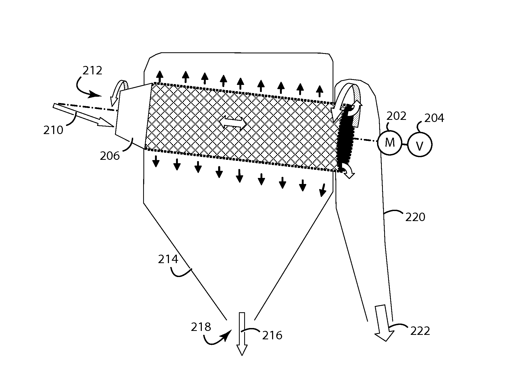
[0039]FIG. 2 represents the present invention, an inclined cylindrical sieve system 200. A speed-controlled motor (M) 202 and a vibrator (V) 204 are attached to spin and vibrate a cylindrical screen 206 that rotates on an inclined axis 208. Being “inclined” implies at least some gravity is present. The rotation rate is set such that the material mix experiences a centrifugal acceleration that is at least 1.5 times the acceleration of gravity so that it is centrifuged onto the rotating cylindrical screen and forms a bed of material that is nearly uniform in thickness around the circumference of the cylindrical screen. A dry mix 210 of granular material is continually introduced inside a small end 212 of the cylindrical screen 206. A fines collection housing 214 catches and collects the fines 216 that pass through cylindrical screen 206. Under gravity, these will drop out below from a spigot 218. A coarse materials chute 220 conducts away the coarse materials 222 that were too large t...
third embodiment
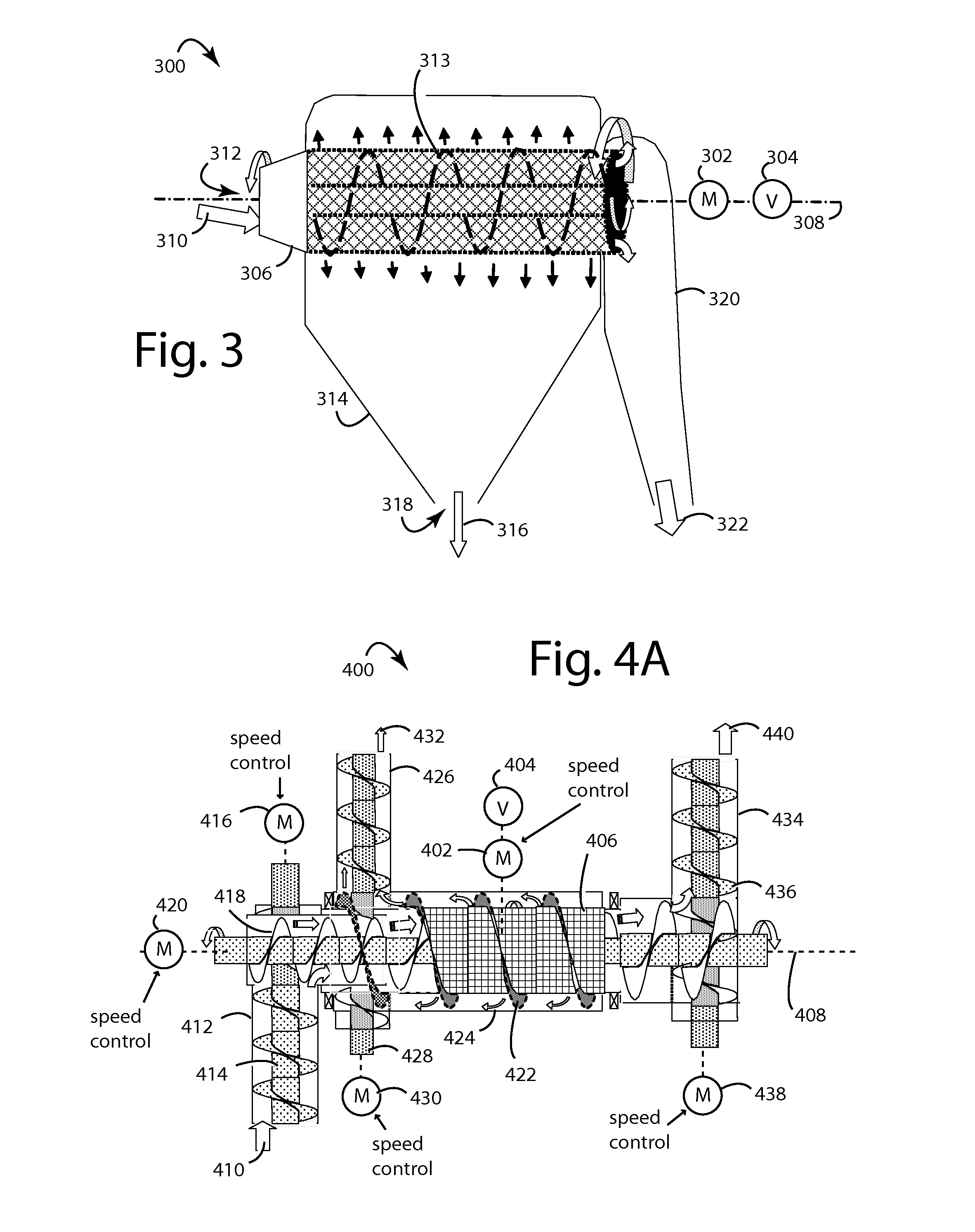
[0041]FIG. 3 represents the present invention, a screw-augured cylindrical sieve system 300. A speed-controlled motor (M) 302 and an optional vibrator (V) 304 are attached to spin and vibrate a cylindrical screen 306 that rotates on a horizontal axis 308. Being “horizontal” implies at least some gravity is present. A dry mix 310 of granular material is continually introduced inside a small end 312 of the cylindrical screen 306. A separately rotated brush or screw auger 313 on a coaxial shaft moves the dry mix 310 along the inside faces of cylindrical screen 306. A fines collection housing 314 catches and collects the fines 316 that pass through cylindrical screen 306. Under gravity, these will drop out below from a spigot 318. A coarse materials chute 320 conducts away the coarse materials 322 that were too large to pass through cylindrical screen 306. The screw auger, gravity, vibration, and centrifugal force all combine on the dry mix 310 to help provide the shearing flows needed ...
PUM
 Abstract
Description
Claims
Application Information
 - R&D Engineer
- R&D Manager
- IP Professional
- Industry Leading Data Capabilities
- Powerful AI technology
- Patent DNA Extraction
Browse by: Latest US Patents, China's latest patents, Technical Efficacy Thesaurus, Application Domain, Technology Topic.
© 2024 PatSnap. All rights reserved.Legal|Privacy policy|Modern Slavery Act Transparency Statement|Sitemap