
Circuit connection pad design for improved electrical robustness using conductive epoxy

a technology of conductive epoxy and connection pad, which is applied in the direction of supporting the head, recording information storage, instruments, etc., can solve the problems of faulty or insufficient electrical connection, faulty electrical connection between the connection pad of the flexible circuit and the surface of the piezoelectric, etc., to improve the electrical connection and improve the control of the actuation of the microactuator

Active Publication Date: 2016-03-24
SEAGATE TECH LLC
View PDF14 Cites 6 Cited by
  • Summary
  • Abstract
  • Description
  • Claims
  • Application Information

AI Technical Summary

Benefits of technology

The invention improves the connection between electrical pads on flexible circuits used in disk drives. This improves the control of microactuators and allows for better positioning of magnetic read / write heads. The electrical connections use conductive epoxy to connect to piezoelectric microactuators, resulting in a more reliable and consistent performance for high data resolution in disk drives.

Problems solved by technology

Intermittent electrical connections can result from faulty or insufficient electrical connection at this electrical pad to epoxy interface.
Faulty electrical connection between the connection pad of the flexible circuit and the surface of the piezoelectric microactuator can result from separation of the silver particles at the interface of the conductive epoxy and the gold plated copper surface of the connection pad.
Resin rich zones are believed to result sometimes during the curing process of the conductive epoxy due to material differences between the copper connection pad and the epoxy.

Method used


Image

  • Circuit connection pad design for improved electrical robustness using conductive epoxy
  • Circuit connection pad design for improved electrical robustness using conductive epoxy
  • Circuit connection pad design for improved electrical robustness using conductive epoxy

Examples


Embodiment Construction

[0038]The foregoing specific embodiments of the present invention as set forth in the specification herein are for illustrative purposes only. Various deviations and modifications may be made within the spirit and scope of the invention without departing from the main theme thereof

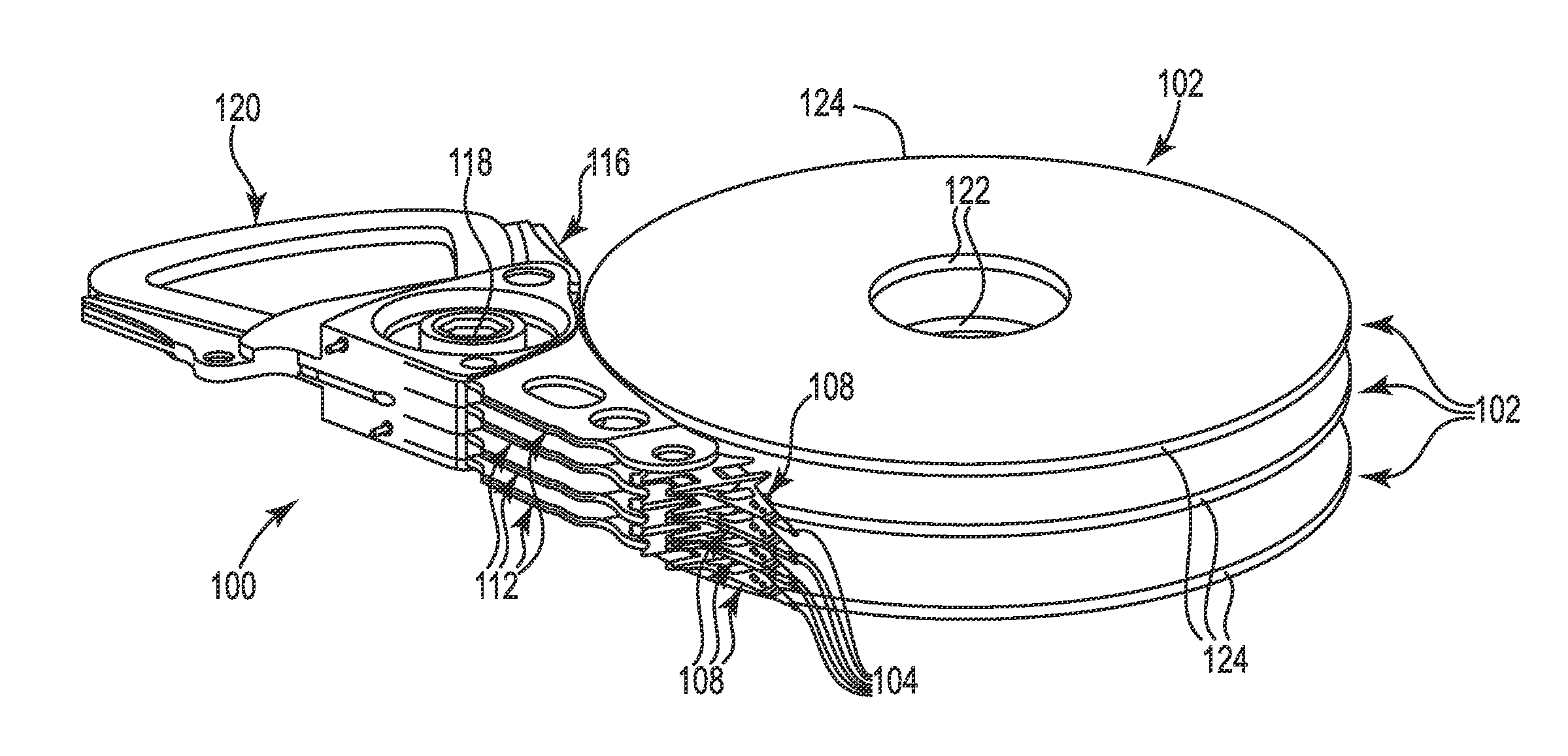
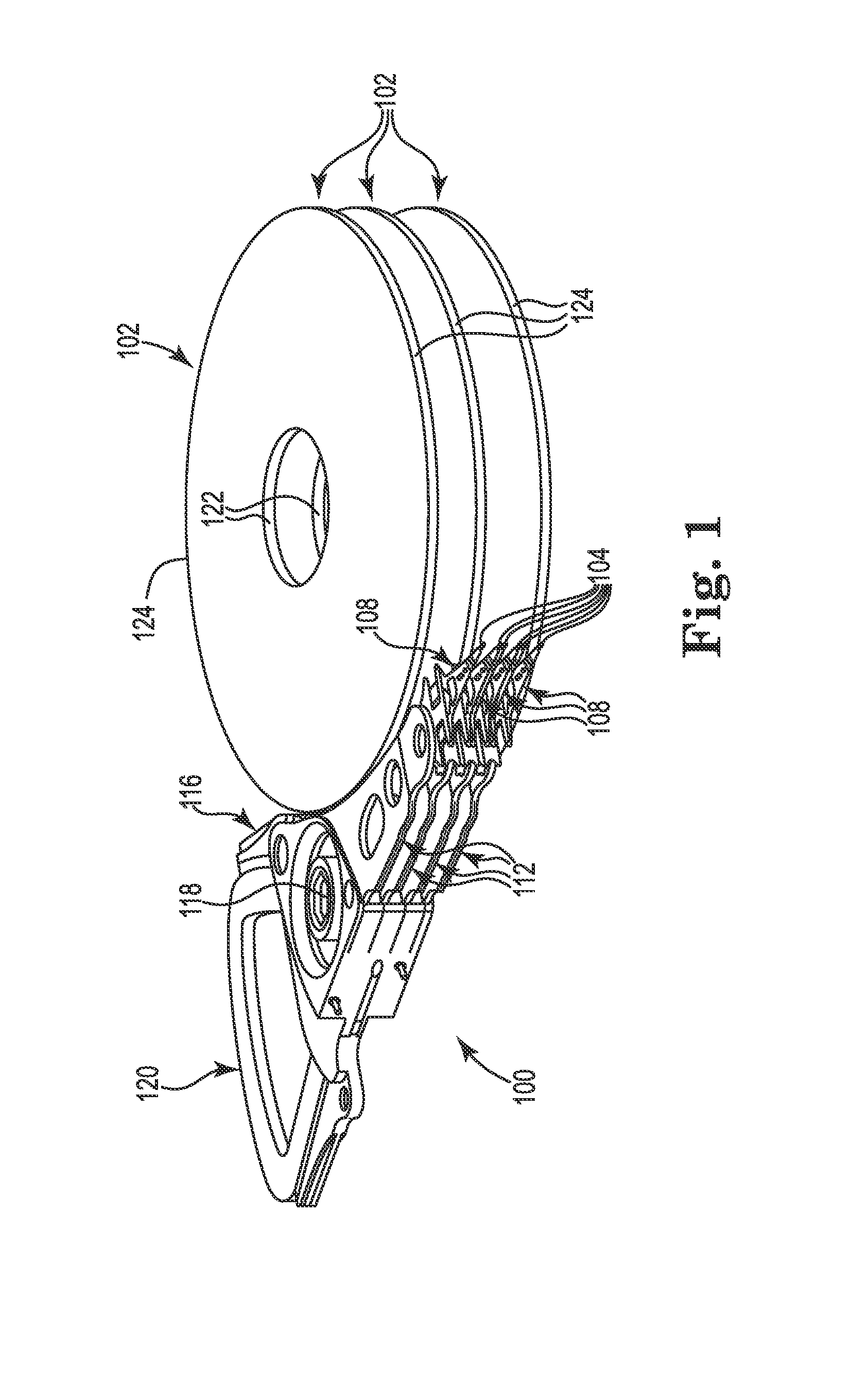
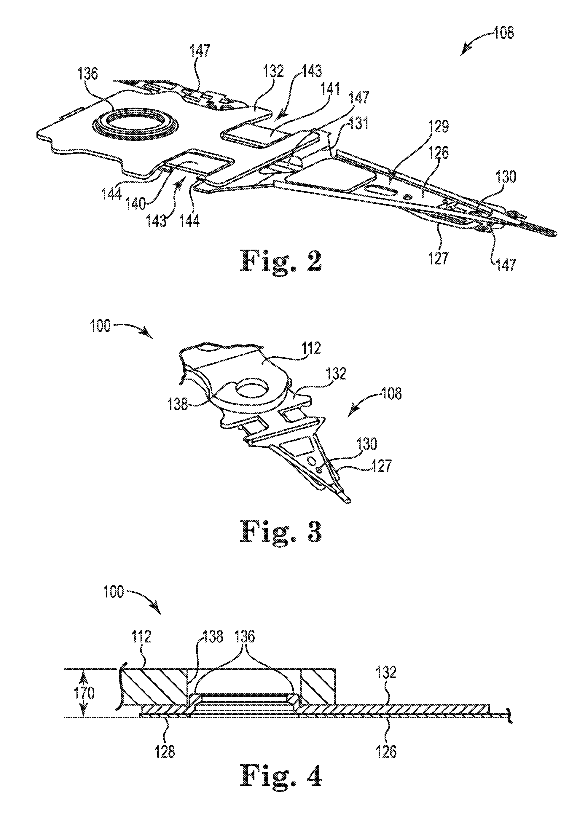
[0039]FIG. 1 illustrates a perspective view of exemplary components of a data storage device including a head stack assembly 100 and media 102. In one embodiment, magnetic media 102 stores information as domains in a plurality of circular, concentric data tracks on data disks as such disks are conventionally mountable to a spindle motor assembly (not shown) that can rotate media 102 and cause its data surfaces to pass under respective bearing slider surfaces. As illustrated, each surface of media 102 has an associated slider 104, each of which slider 104 carries a magnetic head comprising read and write transducers that communicate with the data tracks of the surfaces of media 102.

[0040]Sliders 104 are eac...


PUM


Abstract

Disk drives including head suspensions within dual stage actuation systems have improved electrical connectivity between electrical connection pads from flexible circuits as are applied to head suspension assemblies with piezoelectric microactuators as also provided to head suspension assemblies. A more robust electrical connection provides for better control of microactuator actuation for fine movements and positioning of magnetic read / write heads relative to disk data tracks as part of dual stage actuated suspension systems. Electrical connections utilize conductive epoxy for physically and electrically connecting electrically conductive trace connection pads with one or more surfaces of piezoelectric microactuators. Electrical connections include better conductivity by utilizing plural surface portions of electrical connection pads. The result is a more robust and predictable performance for high data resolution within disk drives.

Description

PRIORITY CLAIM[0001]The present non-provisional Application claims the benefit of commonly owned provisional Application having serial number 62 / 053,356, filed on Sep. 22, 2014, which provisional Application is incorporated herein by reference in its entirety.FIELD OF THE INVENTION[0002]The present invention relates to aspects of head suspension assemblies as are utilized for movably supporting a head within a disk drive, and in particular to head suspension assemblies that include a piezoelectric microactuator for fine head adjustability. The present invention is more particularly directed to electrical connections between such microactuators and conductor elements of such head suspension assemblies.BACKGROUND OF THE INVENTION[0003]Disk drives as data storage devices typically comprise a stack of rotatable disks to which data is written and read by way of magnetic heads that are movably supported with respect to surfaces of the disks by a like number of head suspension assemblies. ...

Claims


Application Information

Patent Timeline
IPC IPC(8): G11B5/48
CPCG11B5/483G11B5/4846G11B5/4833G11B5/486
Inventor BERSCHEIT, GARYBRANDTS, JACKSON
Owner SEAGATE TECH LLC
Learn More