Sample rate converter and method of converting sample rate

a sample rate converter and sample rate technology, applied in the direction of synchronisation signal speed/phase control, digital transmission, system details, etc., can solve the problems of deterioration of performance, ineffectiveness, and increase in the complexity of filters

Active Publication Date: 2016-03-24
ELECTRONICS & TELECOMM RES INST
View PDF0 Cites 11 Cited by
  • Summary
  • Abstract
  • Description
  • Claims
  • Application Information

AI Technical Summary

Benefits of technology

[0030]Correcting, by the resample position compensation unit, the error value of the signal attributable to the non-integer multiple sample rate conversion by applying the value of the resample position to the signal may include minimizing the influence of a phase offset generated between asynchronous clocks by predicting the location of the memory in which the signals to be sampled are stored and the resample position of the signal through the calculation of the cumulative value of a received resample ratio.

Problems solved by technology

Although this sample rate conversion algorithm is the easiest rate conversion method, it is not effective because the complexity of the filter increases if the values L and M are increase.
However, in a sample rate conversion algorithm used for resampling in a structure in which two asynchronous clocks operate at the same time, the resampling using a fractional delay filter causes the deterioration of performance because problems, such as metastability, a phase offset, and a clock rate error, occur.
However, there still remains the problem in which an error occurs between an externally input resample ratio and an actual operating clock rate.
However, the related art does not discloses a feature in which an accurate resampling position is found by compensating for the error of a resample ratio input to a fractional delay filter in a sample rate conversion algorithm that supports a fractional resample ratio and uses asynchronous clocks.

Method used


Image

  • Sample rate converter and method of converting sample rate
  • Sample rate converter and method of converting sample rate
  • Sample rate converter and method of converting sample rate

Examples


Embodiment Construction

[0042]The present invention may be subjected to various modifications and have various embodiments. Specific embodiments are illustrated in the drawings and described in detail below. However, it should be understood that the present invention is not intended to be limited to these specific embodiments but is intended to encompass all modifications, equivalents and substitutions that fall within the technical spirit and scope of the present invention.

[0043]The terms used herein are used merely to describe embodiments, and not to limit the inventive concept. A singular form may include a plural form, unless otherwise defined.

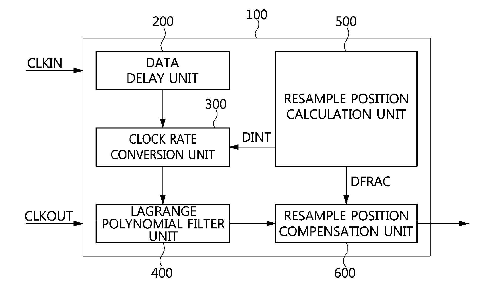
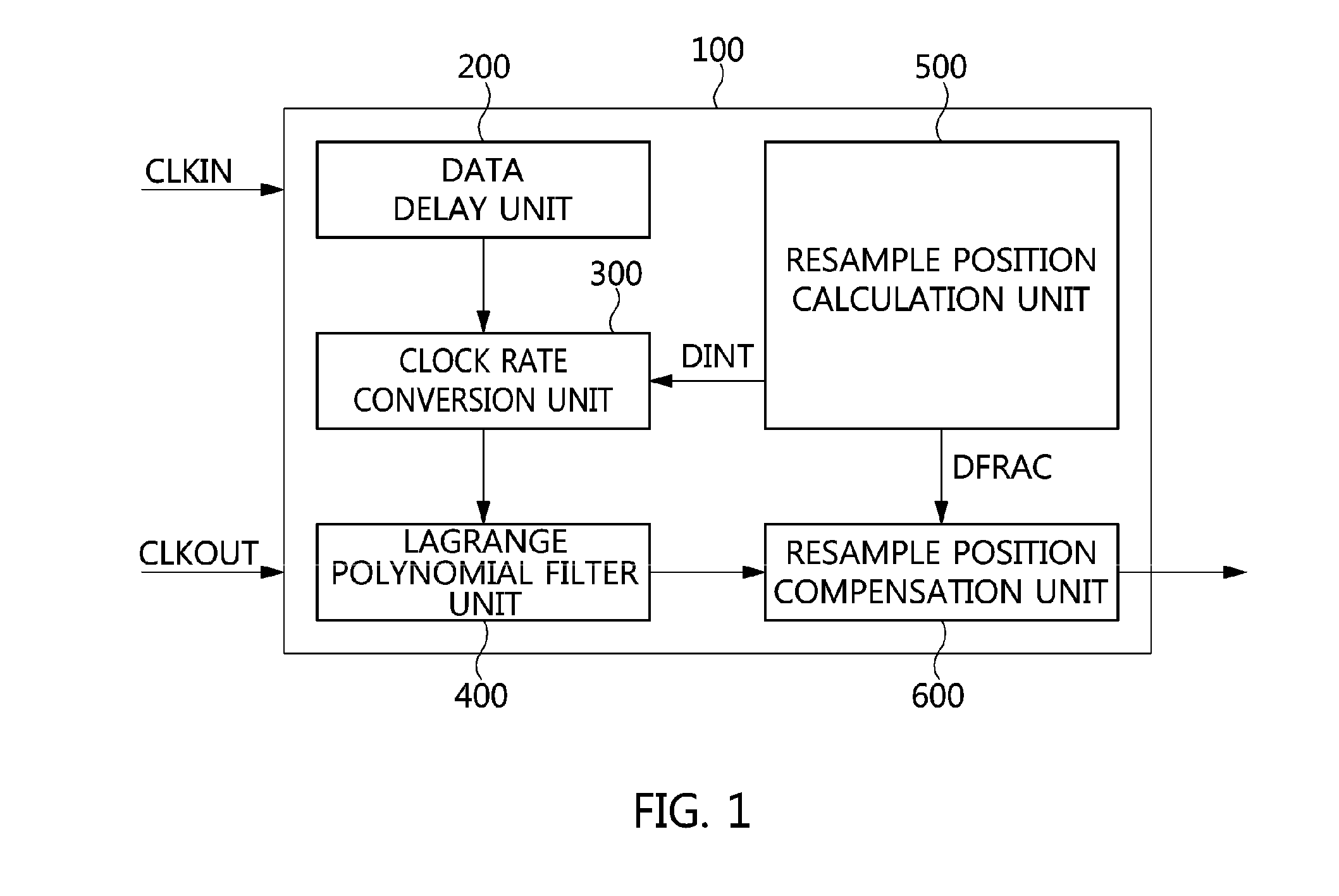
[0044]In an embodiment of the present invention, the configuration of a sample rate converter 100 for converting the sample rate of signals in a digital signal processing system using asynchronous clocks is described below.

[0045]The sample rate converter 100 based on a fractional delay filter resamples input signals, sampled at an input clock rate, into signals a...


PUM


Abstract

A sample rate converter and a method of converting a sample rate are disclosed herein. The sample rate converter includes a data delay unit, a clock rate conversion unit, a Lagrange polynomial filter unit, a resample position calculation unit, and a resample position compensation unit. The data delay unit delays signals in response to an input clock signal. The clock rate conversion unit converts the sample rate of the signals. The Lagrange polynomial filter unit performs a filtering function on the signals whose rate has been converted. The resample position calculation unit outputs the value (Dint, dfrac) of the resample position of the signals based on a set resample ratio value. The resample position compensation unit corrects the error value of the signals by applying the value (Dint, dfrac) to the signals, and outputs a final signal.

Description

CROSS-REFERENCE TO RELATED APPLICATION[0001]This application claims the benefit of Korean Patent Application No. 10-2014-0124737, filed Sep. 19, 2014, which is hereby incorporated by reference herein in its entirety.BACKGROUND[0002]1. Technical Field[0003]Embodiments of the present invention relate to a resample ratio error compensation technique for a sample rate conversion algorithm that supports a non-integer rational number multiple resample ratio.[0004]2. Description of the Related Art[0005]In digital signal processing systems, if a radio frequency (RF) band clock has not been synchronized with a baseband clock, a sample rate conversion algorithm is used to change the rate of a signal to a low baseband sampling frequency while maintaining information. In particular, systems supporting various communication standards and frequency bands need to support a non-integer multiple sampling ratio as well as an integer multiple sampling ratio.[0006]As a related sample rate conversion al...

Claims


Application Information

Patent Timeline
Patent Type & Authority Applications(United States)
IPC IPC(8): H04L7/04
CPCH04L7/048H04L25/05H03H17/028H03H17/0628
Inventor KIM, SANG-KYUNPARK, MI-JEONGEO, IK-SOO
Owner ELECTRONICS & TELECOMM RES INST
Why Eureka
Try Eureka