Deformable mirror system, control method therefor, and ophthalmic apparatus

a deformable mirror and control method technology, applied in the field of deformable mirror systems, control methods therefor, and ophthalmic apparatuses, can solve problems such as troublesome nonlinearity of deformable mirrors, aberration of eyeballs, and hindering eyeball observation, so as to reduce the time it takes for reflected light

Active Publication Date: 2016-03-31
CANON KK
View PDF1 Cites 49 Cited by
  • Summary
  • Abstract
  • Description
  • Claims
  • Application Information

AI Technical Summary

Benefits of technology

[0009]The present invention has been made in view of the above-mentioned circumstances, and therefore has an object to reduce the time it takes for reflected light from a deformable mirror system utilized in an AO unit to reach a desired light wavefront shape.

Problems solved by technology

However, for the reason that refractive indices of the cornea and the lens are not uniform and other such reasons, measuring light or the like that has passed through the eyeball has aberration, and the aberration may hinder the observation of the eyeball.
In an ophthalmic apparatus such as a fundus observation apparatus using recent AO technologies, it is required to perform correction of various diopters such as myopia and hyperopia of a patient by the deformable mirror, but there are many problems for the realization.
Among others, in a case where a high diopter is to be corrected, nonlinearity of the deformable mirror may become problematic.
However, in the related-art example described in Japanese Patent Application Laid-Open No. 2007-25503 above, a large number of calculations are required to update the voltage template as the need arises, and it takes long time to obtain a desired shape of the deformable mirror.

Method used


Image

  • Deformable mirror system, control method therefor, and ophthalmic apparatus
  • Deformable mirror system, control method therefor, and ophthalmic apparatus
  • Deformable mirror system, control method therefor, and ophthalmic apparatus

Examples


first embodiment

Fundus Imaging Apparatus

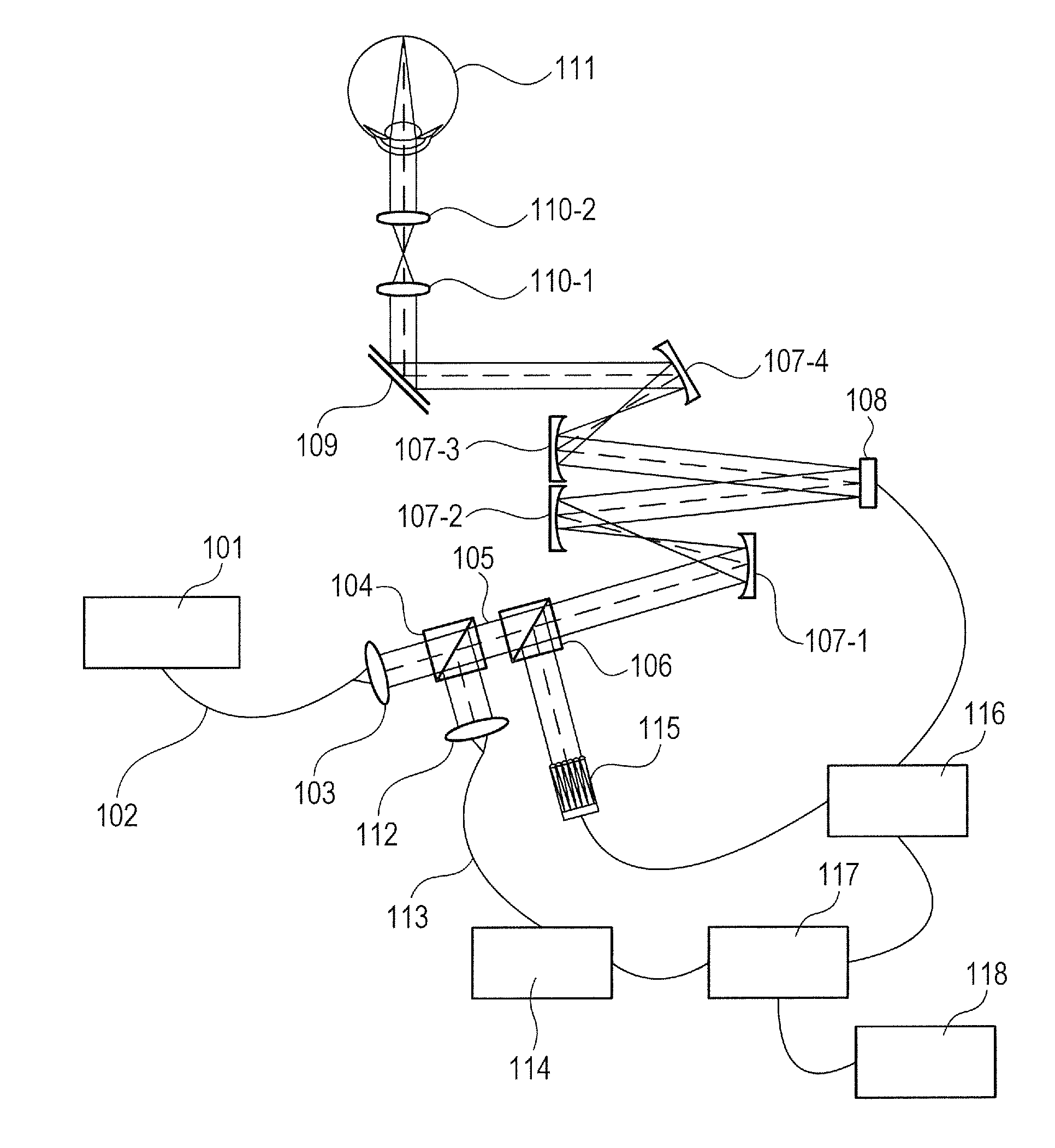
[0024]A configuration of a fundus imaging apparatus to which a deformable mirror system according to the present invention is applied is described with reference to FIG. 1. Note that, in this embodiment, an object to be inspected, which is a measurement target, is an eye, and aberration of light wavefront generated by the eye to be inspected is corrected by an AO unit to capture an image of a fundus.

[0025]Moreover, in FIG. 1, the deformable mirror system according to the present invention includes a deformable mirror 108, a wavefront sensor 115, and an AO control unit 116. The deformable mirror 108 changes a shape of a reflecting surface by a deformation amount in accordance with an input signal, which is to be described later. The wavefront sensor 115 functions as a light wavefront measurement unit configured to measure a light wavefront shape of reflected light from the deformable mirror 108. The AO control unit 116 functions as a conversion factor calculat...

second embodiment

Fundus Imaging Apparatus

[0066]A second embodiment of the present invention is described with reference to a flow chart of FIG. 9 by way of an example of a control method for a fundus imaging apparatus in a mode which is different from the first embodiment and to which the present invention is applied. In this embodiment, a basic apparatus configuration is similar to that in the first embodiment. Therefore, a description of the apparatus configuration is omitted, and a diopter correction process, which is characteristic in this embodiment, is described in detail.

[0067]FIG. 9 is a flow chart for performing the diopter correction process in this embodiment, and a basic flow is similar to that in FIG. 5. Therefore, a step that is different from the above-mentioned process is described here. After measuring the light wavefront shape of the reflected light or the like from the eye 111 in Step S207, the defocus amount is obtained based on the image obtained by the light intensity sensor 11...

third embodiment

Fundus Imaging Apparatus

[0074]A third embodiment of the present invention is described with reference to a flow chart of FIG. 10 by way of an example of a control method for a fundus imaging apparatus in a mode which is different from the first embodiment and to which the present invention is applied. In this embodiment, a basic apparatus configuration is similar to that in the first embodiment. Therefore, a description of the apparatus configuration is omitted, and a diopter correction process, which is characteristic in this embodiment, is described in detail.

[0075]FIG. 10 is a flow chart for performing the diopter correction process in this embodiment, and a basic flow is similar to that in FIG. 5. Therefore, a step that is different from the above-mentioned process is described here. After measuring the light wavefront shape of the reflected light or the like from the eye 111 in Step S207, it is determined in Step S601 whether a root mean square (rms) value of an included high-o...


PUM


Abstract

For reducing a time utilized in an AO process, provided is a deformable mirror system, including: a deformable mirror capable of changing a shape of a reflecting surface by a deformation amount in accordance with an input signal; a light wavefront measurement apparatus configured to measure a light wavefront shape of reflected light from the deformable mirror; a conversion factor calculation apparatus configured to calculate a conversion factor used in obtaining the input signal from a variation in light wavefront shape of the reflected light with respect to a change in input signal; a shape difference calculation apparatus configured to calculate a shape difference between the light wavefront shape measured by the light wavefront measurement apparatus and a light wavefront shape calculated from the input signal; and a conversion factor update unit configured to update the conversion factor in accordance with the calculated shape difference.

Description

BACKGROUND OF THE INVENTION[0001]1. Field of the Invention[0002]The present invention relates to a deformable mirror system forming an adaptive optics system used in an astronomical telescope, a fundus observation apparatus, or the like, and to an ophthalmic apparatus using the deformable mirror system.[0003]2. Description of the Related Art[0004]Currently, as ophthalmic equipment, various kinds of optical equipment are used. Among others, as optical equipment for observing an eye, various kinds of equipment such as an anterior ocular segment imaging apparatus, a fundus camera, a confocal scanning laser ophthalmoscope (SLO), and an optical coherence tomography (OCT) apparatus are used.[0005]An eyeball as an object to be observed is formed of a cornea, aqueous humor, a lens, a vitreous body, and a retina, and may be viewed as four lenses cemented together. However, for the reason that refractive indices of the cornea and the lens are not uniform and other such reasons, measuring ligh...

Claims


Application Information

Patent Timeline
Patent Type & Authority Applications(United States)
IPC IPC(8): A61B3/12A61B3/10A61B3/14G02B26/08
CPCA61B3/12A61B3/1015A61B3/14G02B26/0825G02B26/06
Inventor TAKENO, KOHEIOHASHI, KAISHI
Owner CANON KK
Why Eureka
Try Eureka