Supercharging system

a supercharging system and supercharging technology, applied in mechanical equipment, machines/engines, electric control, etc., can solve problems such as malfunction diagnosis, malfunction diagnosis, and difficulty in removing the influence of turbo lag, and achieve the effect of increasing the time required for malfunction diagnosis, increasing the diagnostic time, and increasing the boost pressure used for diagnosis

Inactive Publication Date: 2016-03-31
TOYOTA JIDOSHA KK
View PDF4 Cites 4 Cited by
  • Summary
  • Abstract
  • Description
  • Claims
  • Application Information

AI Technical Summary

Benefits of technology

[0009]This invention is to provide a supercharging system that is less likely or unlikely to suffer from an influence of a turbo lag on the result of diagnosis, and is able to perform malfunction diagnosis with high accuracy.
[0014]Thus, malfunction diagnosis is not performed using only a parameter obtained at a certain point in time, but is performed using the parameter having a positive relationship with the integrated intake air amount that reflects the change hi story of the intake air amount during the integration period. Therefore, with the above arrangement, even if a turbo lag is not eliminated, the system is less likely or unlikely to suffer from the influence of the turbo lag on the result of diagnosis, and is able to perform the malfunction diagnosis with high accuracy.
[0017]In the supercharging system, the precondition may include a condition that an amount of change of the intake air amount per unit time is within a predetermined range. When the amount of change of the intake air amount per unit time is too small, the amount of change of the boost pressure per unit time is reduced. Therefore, a difference is less likely or unlikely to appear between the boost pressure in the case where a malfunction occurs in the waste gate valve, and the boost pressure in the case where there is no malfunction in the valve, and the accuracy in malfunction diagnosis based on the boost pressure may be reduced. Also, when the amount of change of the intake air amount per unit time is too large, a turbo lag becomes extremely large. Therefore, the accuracy in malfunction diagnosis may be reduced even when the parameter having a positive correlation with the integrated intake air amount is used.
[0021]In the supercharging system, the electronic control unit may be configured to store the boost pressure detected when the integration period elapses, as the first boost pressure or the second boost pressure. As the period from the time when the integration periods ends to the time when the boost pressure used for diagnosis is obtained is longer, the length of time required to obtain the first boost pressure or the second boost pressure is increased, and the time required to perform malfunction diagnosis is increased. Also, the period from the end of the integration period to the time when the boost pressure used for diagnosis is obtained is longer, an influence of the energy received by the turbine until the boost pressure is obtained, on the boost pressure, is increased. Therefore, as the period from the end of the integration period to the time when the boost pressure used for diagnosis is obtained is longer, the parameter having a positive correlation with the integrated intake air amount becomes less correlated with the boost pressure actually obtained. Namely, as the period from the end of the integration period to the time when the boost pressure used for diagnosis is obtained is longer, the accuracy of malfunction diagnosis using the first boost pressure and the second boost pressure is reduced. On the other hand, in the system as described above, malfunction diagnosis is performed based on the boost pressure detected at the point in time at which the integration period elapses. Therefore, the malfunction diagnosis can be promptly performed with high accuracy.

Problems solved by technology

Even if various parameters are obtained at the time when the fixed transient period elapses, as described in JP 2014-074386 A, it may be difficult to remove an influence of the turbo lag.
As a result, malfunction diagnosis may not be appropriately conducted in a diagnostic method in which parameters obtained in a condition where the turbo lag is eliminated are supposed to be used, and the accuracy in malfunction diagnosis may vary depending on operating conditions.
Accordingly, it may be difficult to adequately perform malfunction diagnosis, even if the intake air amount, etc. are estimated from various parameters obtained upon the lapse of the fixed transient period, and malfunction diagnosis of the waste gate valve is conducted based on the estimated intake air amount, etc., as in the system of JP 2014-074386 A.
Thus, it is not realistic to set such a long transient period.

Method used


Image

  • Supercharging system
  • Supercharging system
  • Supercharging system

Examples


Embodiment Construction

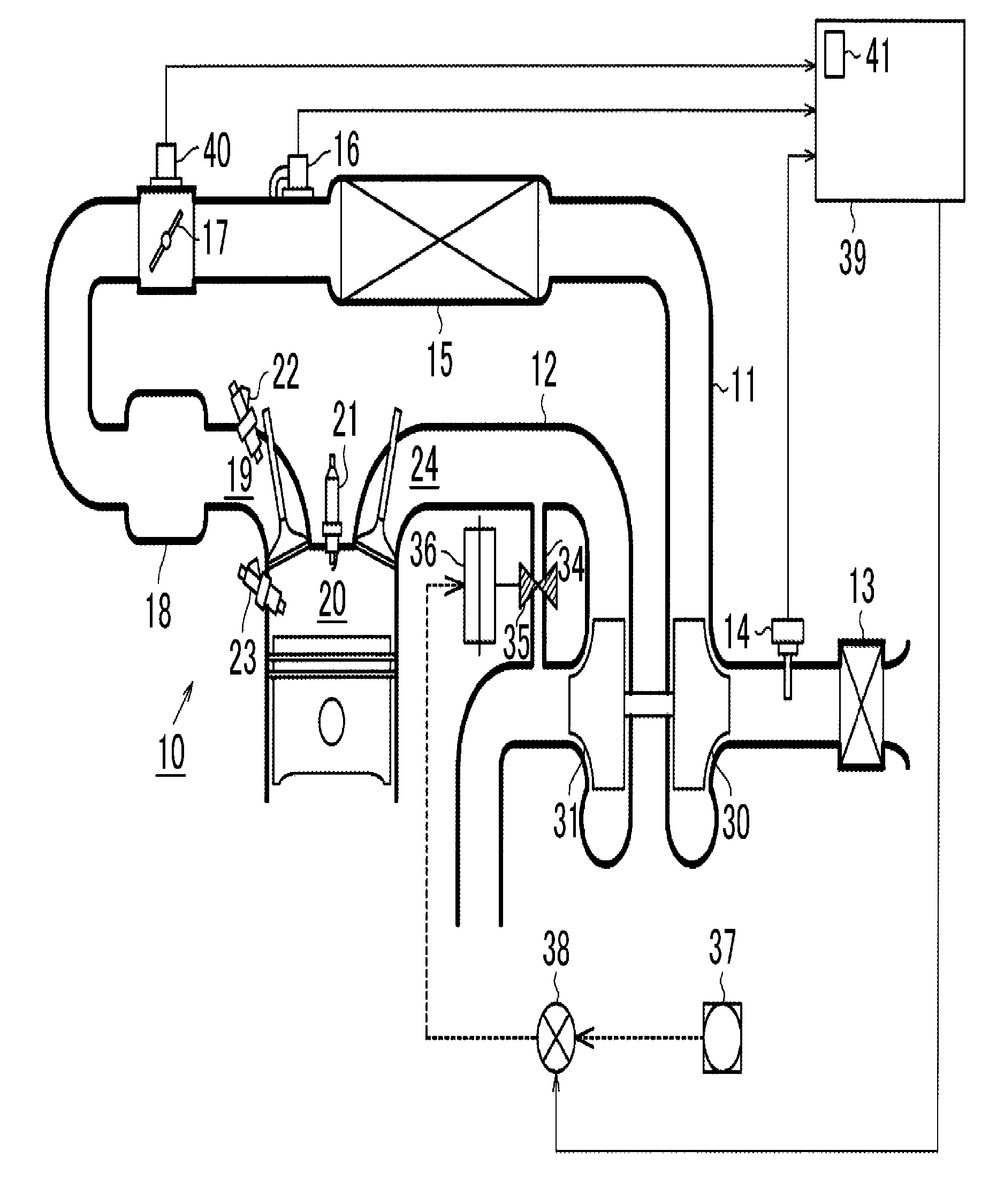
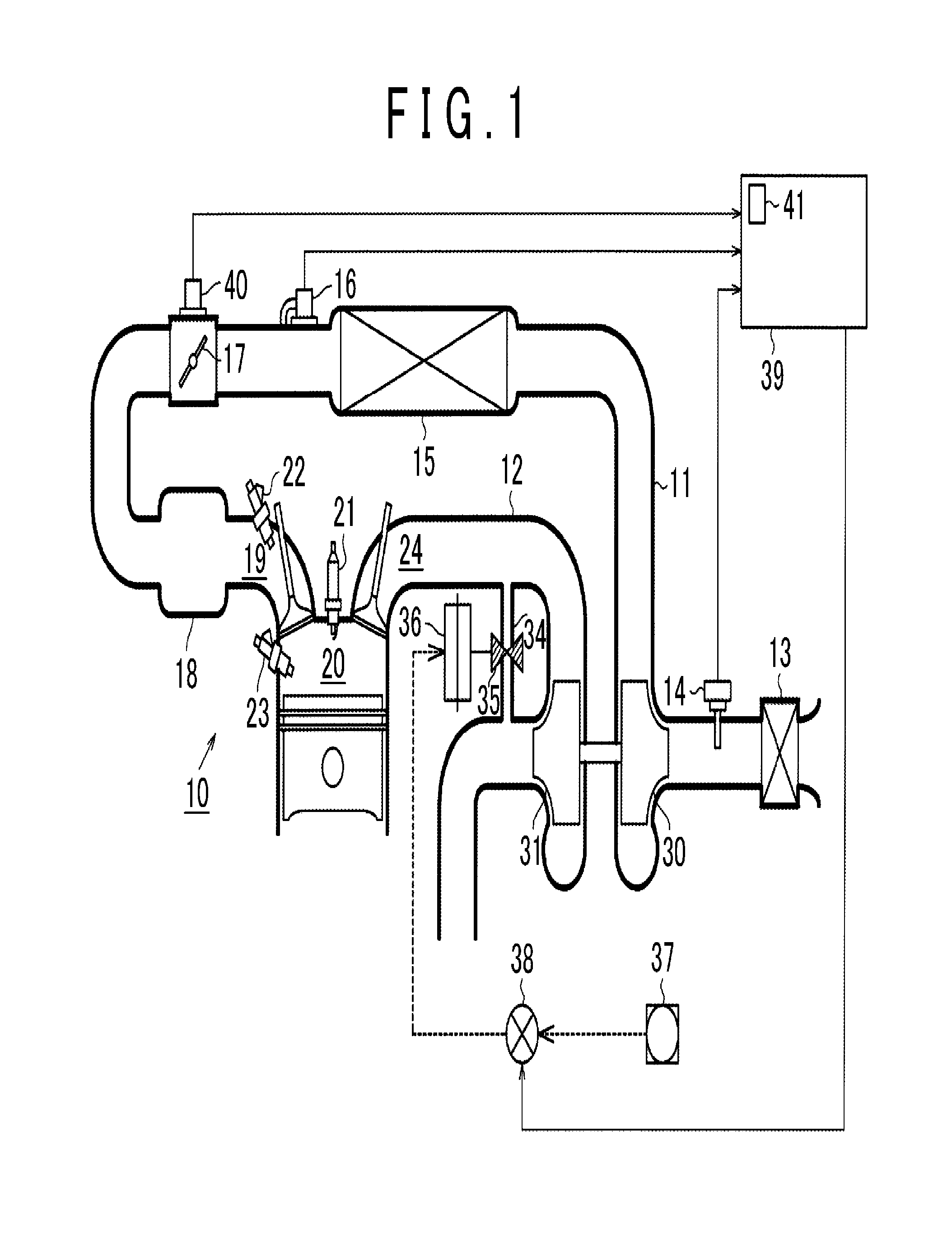
[0035]Referring to FIG. 1 through FIG. 8, a supercharging system according to one embodiment of the invention will be described in detail. As shown in FIG. 1, the supercharging system of this embodiment has an exhaust gas turbine supercharger including a compressor 30 installed in an intake passage 11 of an internal combustion engine 10, and a turbine 31 installed in an exhaust passage 12 of the engine 10. The compressor 30 and the turbine 31 are mechanically coupled to each other. The compressor 30 is arranged to be driven in accordance with operation of the turbine 31 due to the momentum of flow of exhaust gas, to perform supercharging operation.

[0036]An air cleaner 13 that cleans intake air, and an air flow meter 14 are installed in a portion upstream of the compressor 30 in the intake passage 11 of the engine 10. The air flow meter 14, which is one example of the first sensor, serves as an intake air amount detector that detects the flow rate (intake air amount GA) of intake air...


PUM


Abstract

A supercharging system includes a waste gate valve and an ECU. The ECU is configured to: calculate a first parameter and a second parameter, each of which has a positive correlation with an intake air amount; obtain a first difference by subtracting a first boost pressure from a second boost pressure; obtain a second difference by subtracting the first parameter from the second parameter; obtain a quotient by dividing the first difference by the second difference; and determine that a malfunction occurs in the waste gate valve when the quotient is larger than a threshold value.

Description

INCORPORATION BY REFERENCE[0001]The disclosure of Japanese Patent Application No. 2014-201243 filed on Sep. 30, 2014 including the specification, drawings and abstract is incorporated herein by reference in its entirety.BACKGROUND OF THE INVENTION[0002]1. Field of the Invention[0003]The invention relates to a supercharging system.[0004]2. Description of Related Art[0005]As one type of supercharging systems used in internal combustion engines, there is a supercharging system that performs supercharging by utilizing exhaust energy. The supercharging system of this type includes a compressor that is installed in an intake passage of the engine, and is operable to pressurize intake air flowing in the intake passage and deliver it into a combustion chamber of the engine, and a turbine that is installed in an exhaust passage of the engine, and operates, due to the momentum of exhaust gas flowing in the exhaust passage, to drive the compressor. Further, the supercharging system of this typ...

Claims


Application Information

Patent Timeline
Patent Type & Authority Applications(United States)
IPC IPC(8): F02D41/00F02D41/22
CPCF02D41/0007F02D2041/228F02D41/22F02M25/0706F02B37/18F02D41/18F02D41/221F02D2200/0406F02M26/04Y02T10/12Y02T10/40
Inventor MATSUMOTO, TAKUYAKATAYAMA, AKIHIRO
Owner TOYOTA JIDOSHA KK
Why Eureka
Try Eureka