On line automatic detection of the time phase of the threshold voltage of a lighting load and its application in lighting management

Active Publication Date: 2016-03-31
CHEN CHIA TEH
View PDF9 Cites 18 Cited by
  • Summary
  • Abstract
  • Description
  • Claims
  • Application Information

AI Technical Summary

Benefits of technology

[0022]The iteration calculation of the other search algorithm is an incremental scheme to gradually increase the time delay of the trigger signal to approach the neighborhood of the time phase of the threshold voltage. When the program codes of the search algorithm are carried out, the microcontroller generates a series of testing trigger signals with increasing time delay starting with a non-zero incremental value. The lighting load detector monitors constantly the conduction/cutoff status of the lighting load whenever a testing trigger signal is activated. The lighting load detector delivers thereof conduction/cutoff status signals recognizable by the microcontroller. The microcontroller generates testing trigger signal with time delay and checks alternately the conduction/cutoff status signal delivered by the lighting load detector. If the status signal signifies a cutoff state of the lighting load, the program codes of the second search algorithm increases the time delay of the testing trigger signal by adding a predetermined small increment to the current time delay. The program codes continue the iteration process by updating time delay increasingly and checking alternately the status signal, until the status signal signifies a conduction state of the lighting load. The iteration process is ended when the microcontroller generates a final trigger signal with a time delay to cause the lighting load detector delivering a status signal to signify a transition of the lighting load from cutoff state to conduction state. The time delay of the final trigger signal is determined by the search algorithm as the time period counted from the zero-crossing point of the AC voltage to the time point when the instant AC voltage is equal to or slightly greater than the threshold voltage of the lighting load. This time delay of the final trigger signal is referred to as the time phase of the threshold voltage of the lighting load. This time phase is then stored in the memory of the microcontroller for updating a data base to be used for establishing a reliable dimmable range in each half-cycle of the AC power source for controlling the illumination of the lighting apparatus. With the capacity of on line detecting the time phase of the threshold voltage of a lighting load the dimming management of an AC lighting load has become much more reliable.
[0023]In a preferred embodiment of the present disclosure, a lighting apparatus rendered with the capacity of on line detecting the time phase or time location of threshold voltage can have a photo sensor and a motion sensor integrated with a dimmer circuit to become a two-level security light such that the lighting apparatus is turned on by the photo sensor at dusk to pe

Problems solved by technology

The problems causing the performance failure of dimming function for any lighting apparatus with an AC lighting load are either due to the change of threshold voltage when the consumers replace a burned out bulb with a

Method used


Image

  • On line automatic detection of the time phase of the threshold voltage of a lighting load and its application in lighting management
  • On line automatic detection of the time phase of the threshold voltage of a lighting load and its application in lighting management
  • On line automatic detection of the time phase of the threshold voltage of a lighting load and its application in lighting management

Examples


Embodiment Construction

[0043]The aforementioned illustrations and following detailed descriptions are exemplary for the purpose of further explaining the scope of the present disclosure. Other objectives and advantages related to the present disclosure will be illustrated in the subsequent descriptions and appended drawings.

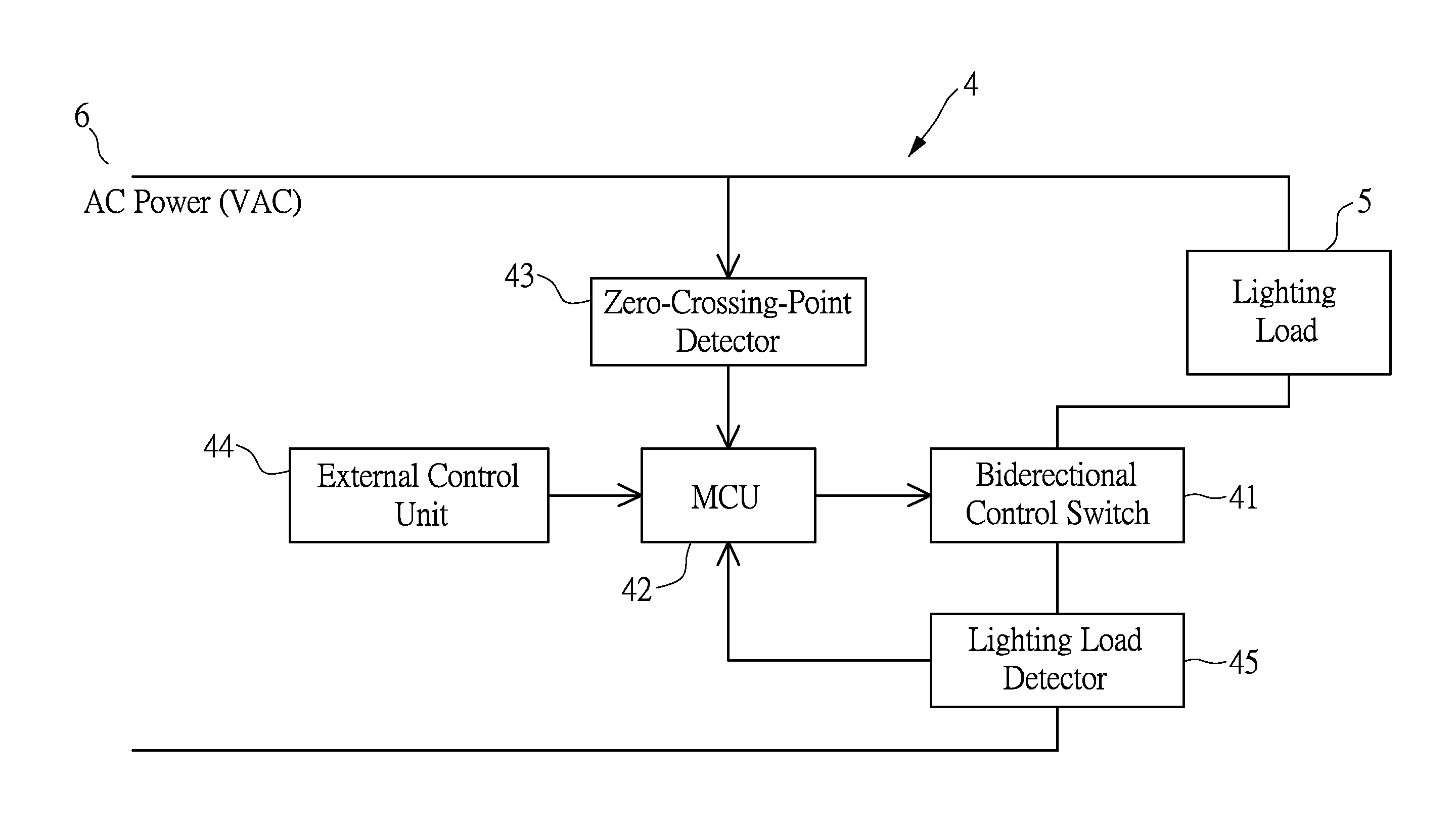
[0044]In accordance with the present disclosure, an on line method is provided to detect the time phase of the threshold voltage of a lighting load. A dimmer circuit, connected in-series with the lighting load and an AC power source, is equipped with this on line method to enhance dimmer functionality, such that the dimmer circuit possesses automatic capacity for self-establishing a workable dimming database without concerning with threshold voltage issue resulted from lighting load.

[0045]Revisit the waveforms of AC voltage and the trigger signal concerned with a dimmer circuit to perform conductive phase angle control. Reference is made to FIG. 4A, where the waveform (a) is a sinusoid...


PUM


Abstract

The present disclosure discloses a method based on microcontroller circuit and software codes to on line automatically detect the time phase of the threshold voltage of a lighting load in each AC half-cycle. This automatic detection capability enables a dimmer circuit of a lighting apparatus to establish a dimmer working range from the self-detected time phase of threshold voltage of the lighting load. The lighting apparatus can be operated with different types of lighting loads to perform a full dimming range from 0% to 100% of maximum lighting output. Therefore, the dimmer circuit makes possible both the lighting fixtures and the users refrained from dimming difficulties caused by different types of lighting loads with different threshold voltages. The design concept can be extended to manage illuminations in a two-level security light on a simple software basis without resorting to complex electric circuits.

Description

CROSS-REFERENCE TO RELATED APPLICATIONS[0001]This application claims priority to U.S. Provisional Patent Application No. 62 / 071,644, filed on 2014 Sep. 30 on behalf of CHIA-THE CHEN, the disclosure of which is incorporated herein by reference in its entirety.BACKGROUND OF THE INVENTION[0002]1. Field of the Invention[0003]The present disclosure relates to automatic detection of electric threshold conduction of lighting load and its application.[0004]2. Description of Related Art[0005]A dimmable lighting apparatus installed outdoors or indoors always comprises lighting bulb(s) with a dimmer circuit. The dimmer circuit is used to control light intensity of electric bulb commonly for energy-saving, creating an aesthetic atmosphere or providing security lighting purposes. In general, the dimmer connected in-series with alternating-current (AC) lighting bulb and AC power is a conductive phase angle control circuit composed of a triac device and a trigger means. Dimmer circuit of this art ...

Claims


Application Information

Patent Timeline
IPC IPC(8): H05B37/02
CPCH05B37/0272H05B37/0227H05B39/044Y02B20/00
Inventor CHEN, CHIA-TEH
Owner CHEN CHIA TEH
Why Eureka
Try Eureka