Low-skew communication system

a communication system and low skew technology, applied in the field of power converters, can solve the problems of high cost of any additional physical link, high board area and component cost, and introduce uncertainty (skew and/or jitter), and achieve the effect of low skew, improved reliability and/or power efficiency, and improved time delay

Active Publication Date: 2016-07-07
MASCHFAB REINHAUSEN GEBR SCHEUBECK GMBH & CO KG
View PDF3 Cites 10 Cited by
  • Summary
  • Abstract
  • Description
  • Claims
  • Application Information

AI Technical Summary

Benefits of technology

[0013]In view of the above, to synchronise the switching of multiple power switching devices, an embodiment may allow a control channel to each of a plurality of switching units to have known latency and further allow low skew between such units. Similar advantages may be found in relation to communications from a switching device or unit to a controller, wherein such communications are for conveying status information and monitoring information.
[0014]Preferably, the first and second predetermined time delays are for substantially (e.g., exactly or approximately) synchronising controlling of the at least one power switching device dependent on the received first signal and controlling of the at least one further power switching device dependent on the received second signal when the first and second signals are transmitted simultaneously. Where each said controlling comprises switching the at least one power switching device on or off, the time delays may thus improve, e.g., reliability and / or power efficiency and / or reduce stress on one or more switching devices at the point of switching.
[0015]In order to provide a known timing delay which is consistent from channel to channel, the first and second predetermined time delays may be substantially equal, to thereby reduce skew between arrival of the first signal at the receive end of the first communications link and arrival of the second signal at the receive end of the second communications link.
[0016]There may further be provided the communications method, wherein the data is sent on the communications channel using a modulation scheme, the method comprising processing, e.g., decoding, a pulse received at a receive end of the communications link as a control or fault signal pulse if the received pulse has duration greater than a predetermined pulse width of the data modulation scheme. Such data may be the first or second data described above. Preferably, the pulse is treated a control / fault pulse if its length is greater than a threshold length, e.g., greater than expected duration of a data pulse of the modulation scheme, e.g., twice the duration of a data pulse. This may allow for some pulse width distortion due for example to propagation conditions. Distinguishing on the basis of pulse width may be considered an example of distinguishing between a control / fault signal and a data signal on the basis of frequency, in this case on the basis of the lower pulse frequency of the control / fault signal compared to the data signal.
[0017]The first (second) delayed data may transmitted onto the communications channel at a predetermined delay after said transmitting said first (second) signal on the communications channel. In this case, the data may not be sent immediately after the control signal has been sent. Rather, a fixed delay for the data transmission may allow known and / or low latency in data transmission, in addition to the improved latency of a control / fault signal as described above. The data and signal may be the first data and signal or the second data and signal. We note however that in embodiments the predetermined delay may not always occur, e.g., where the signal has a high frequency and takes precedence such that the data could be delayed indefinitely rather than having a the predetermined delay and / or if there is a clash in the buffer—if the signal has another transition shortly after a first transition than the data may be delayed again.

Problems solved by technology

However, the cost of any additional physical link is high, both in terms of board area and component cost.
If there is only one clock domain, then signals and data to not need to cross timing boundaries, which generally introduces uncertainty (skew and / or jitter) as the signals are retimed.
In such an embodiment, the signal buffer preferably delays transmission of the received control signal from the transmitter, and the data buffer similarly may delay transmission of the received data from the transmitter.

Method used


Image

  • Low-skew communication system
  • Low-skew communication system
  • Low-skew communication system

Examples


Embodiment Construction

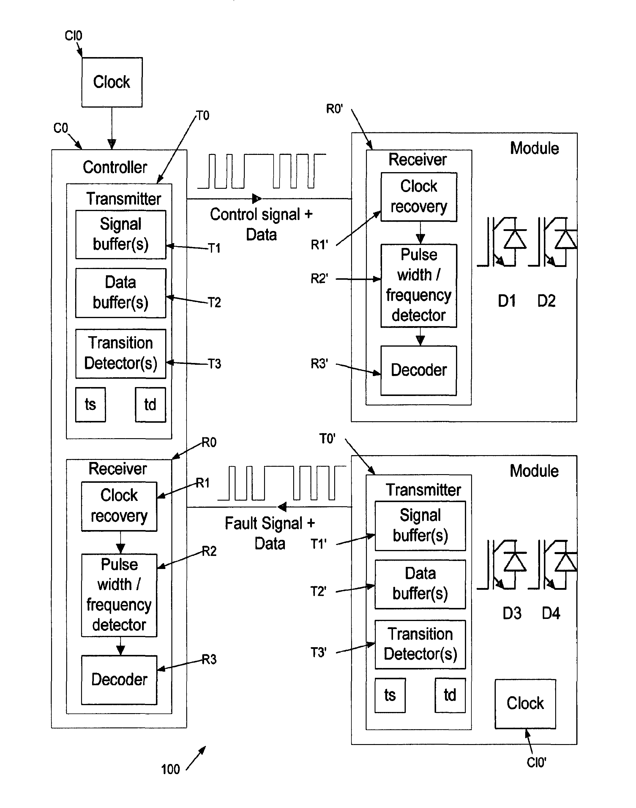
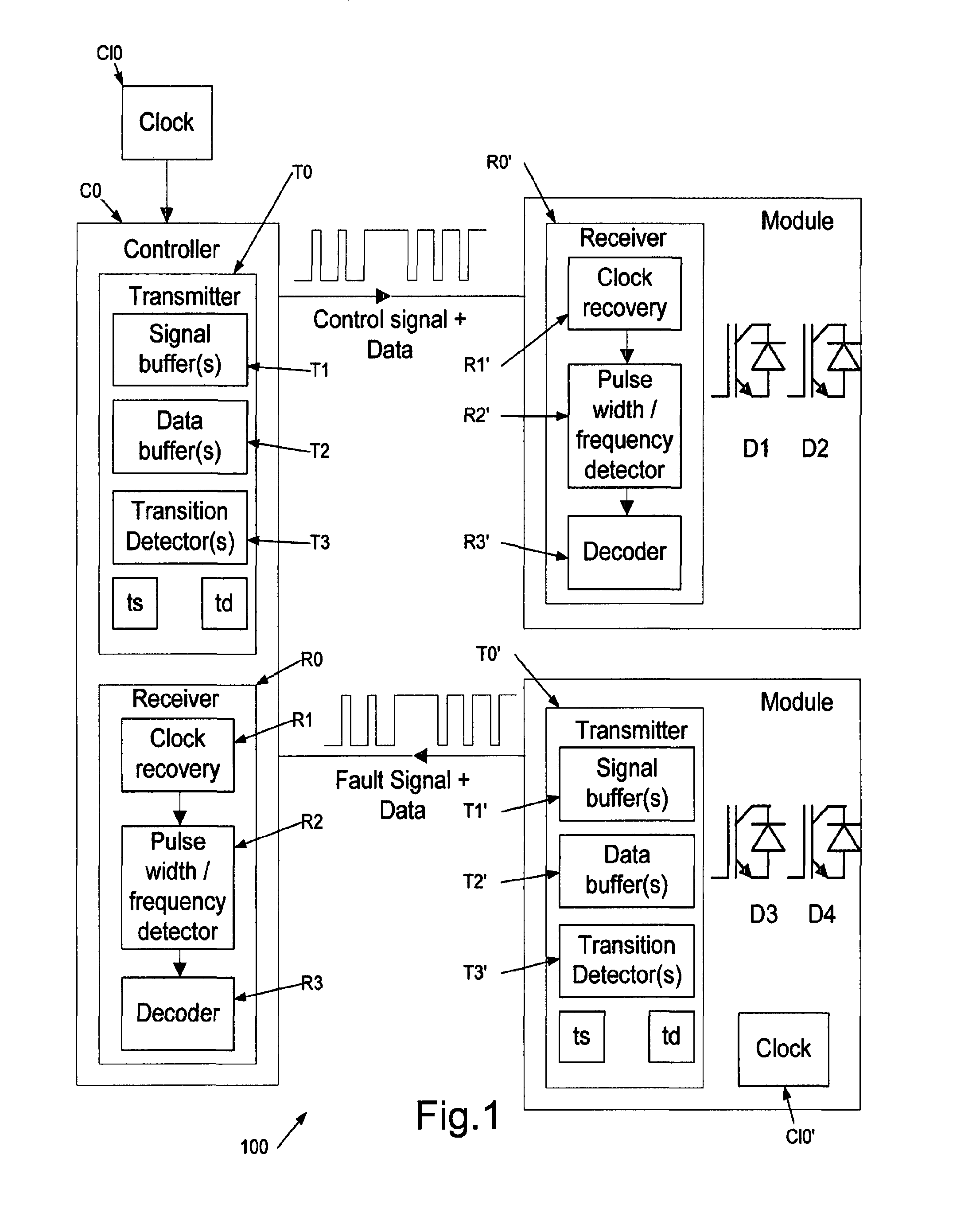
[0048]An embodiment provides a communication method applicable to a power converter such as an AC to DC converter or a DC to AC inverter. Merely for example, FIG. 9 shows a multiple phase leg inverter having two IGBTs stacked in each of the upper and lower sides of each phase leg. A single- or multiple phase leg inverter may be provided as the power switching apparatus 4 of FIG. 10(a) comprising on the device side one or more phase legs having IGBTs coupled to be controlled by gate drivers 2. The device drivers are each coupled to be controlled by a gate driver controller 1 on the control side.

[0049]The power switching devices 5a, 5b of FIG. 10(a) are shown as IGBTs, however may additionally or alternatively comprise one or more FETs (e.g., MOSFETS or JFETs), LILETs, SCRs, etc. . . . . Each such device 5a, 5b is shown as having an optional freewheel diode connected in parallel, for protection of the switching device against reverse voltages and currents.

[0050]Coupling between each d...


PUM


Abstract

The invention generally relates to power converters, and more particularly to a communications method for controlling at least one power switching device of a power converter, a communications system for a power converter, and a power converter comprising the communications system. For example there is provided a communications method for controlling at least one power switching device of a power converter, the method comprising: inputting a signal to a transmit end of a communications link; inputting data to the transmit end of the communications link; determining whether the signal comprises a transition; when said determination indicates that the signal comprises a transition, transmitting the signal comprising the transition into a communications channel of the communications link, wherein the transmitted signal is delayed by a predetermined time delay relative to the inputted signal, said predetermined time delay to allow said determining; transmitting the data on the communications channel, wherein when said determination indicates that the signal comprises a transition the transmitting the data is delayed until after said transmitting the signal; and if the signal has been transmitted, receiving the transmitted signal at the receive end of the communications link and controlling at least one said power switching device dependent on said received signal.

Description

FIELD OF THE INVENTION[0001]The present invention generally relates to power converters, and more particularly to a communications method for controlling at least one power switching device of a power converter, a communications system for a power converter, and a power converter comprising the communications system.BACKGROUND TO THE INVENTION[0002]A communications system may be used to connect together components of a power converter, such as an AC to DC converter or a DC to AC inverter. The converter may be for applications ranging from low voltage chips, to computers, locomotives and high voltage transmission lines. More specific example applications are for switching in high voltage dc transmission lines of the type which may, for example, carry power from an offshore wind installation, and medium voltage (for example greater than 1 KV) switching for motors and the like, for example locomotive motors.[0003]The components of the converter connected by the communications system mi...

Claims


Application Information

Patent Timeline
Patent Type & Authority Applications(United States)
IPC IPC(8): H02M7/00G05B15/02H02M1/00
CPCG05B15/02H02M7/00H04L12/40013H04L25/493G06F13/4295Y02D10/00H02M1/0012
Inventor LEEDHAM, ROBERT JOHNVIT, MATTEOPARKER, STEPHENCRONIN, IVAN
Owner MASCHFAB REINHAUSEN GEBR SCHEUBECK GMBH & CO KG
Why Eureka
Try Eureka