
Connection for a morcellator

a technology of morcellator and connection, which is applied in the field of connection of morcellator, can solve the problems of inflexible protective sleeves, inability to connect to the handpiece in a simple manner, and inconvenient prevention of known protective sleeves

Active Publication Date: 2016-04-07
TROKAMED
View PDF1 Cites 15 Cited by
  • Summary
  • Abstract
  • Description
  • Claims
  • Application Information

AI Technical Summary

Benefits of technology

The invention relates to a protective sleeve for use in minimally invasive surgery. The sleeve has a connecting element with a position indicator in the form of a bead, which helps position the covering of the flange cam and makes it easier for the user to transfer the flange cam to another recess of the flange ring. The connecting element can be uncoupled to transfer the flange cam, making the operation easier for the user. The sleeve can be rapidly adapted to various situations and requirements of modern minimally invasive surgical practice, and a rapid-action closure allows for a quick connection and disconnection of the lock unit and protective sleele or connecting device. The protective sleeve is lightweight and short but can still provide a gas-tight separation between the body cavity and the operating theater.

Problems solved by technology

Firstly, they cannot be connected to the handpiece in a simple manner.
Secondly, known protective sleeves are not suitable for preventing gas from passing therethrough if the medical appliance is not mounted in the protective sleeve and therefore seals off the latter.
Furthermore, known protective sleeves are inflexible in that they are not suitable for use with medical appliances having diameters which greatly differ from one another.
It is also frequently not possible to ensure a sealing function for medical appliances having diameters which greatly differ from one another.

Method used


Image

  • Connection for a morcellator
  • Connection for a morcellator
  • Connection for a morcellator

Examples


Embodiment Construction

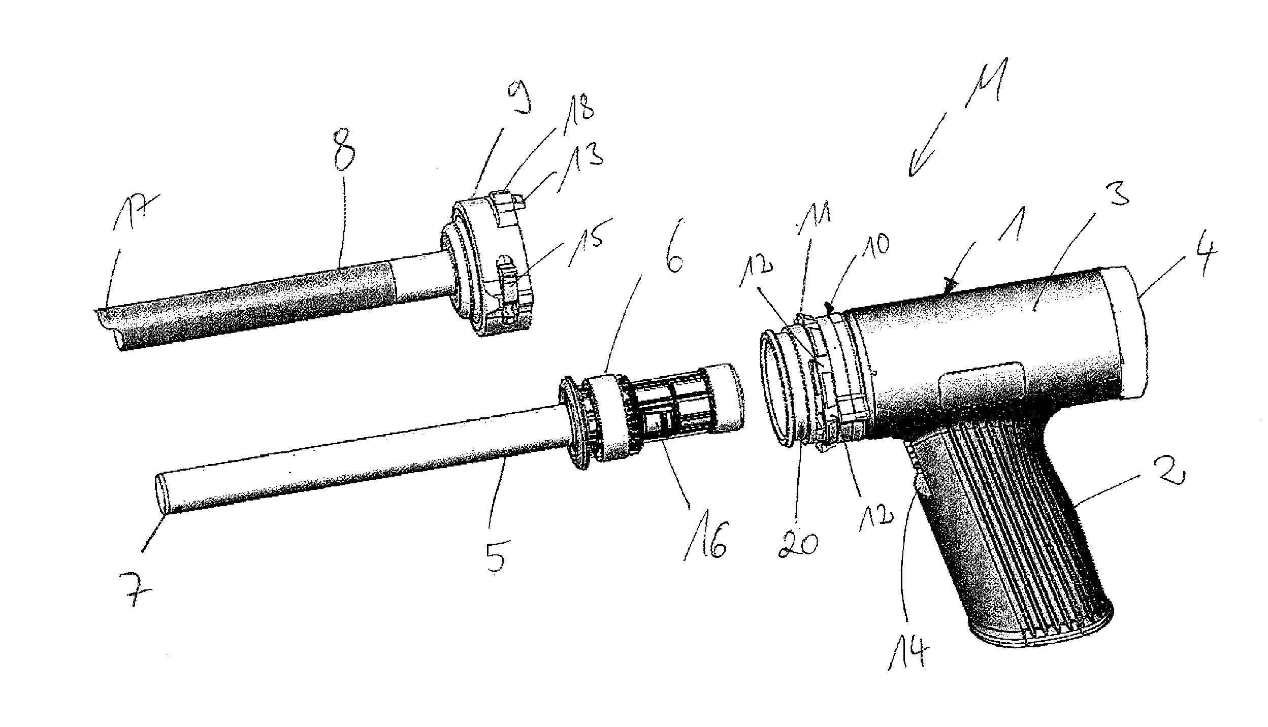
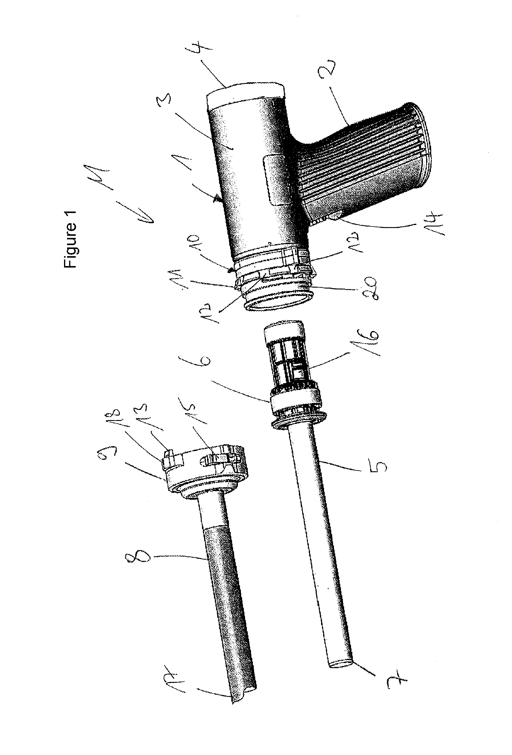
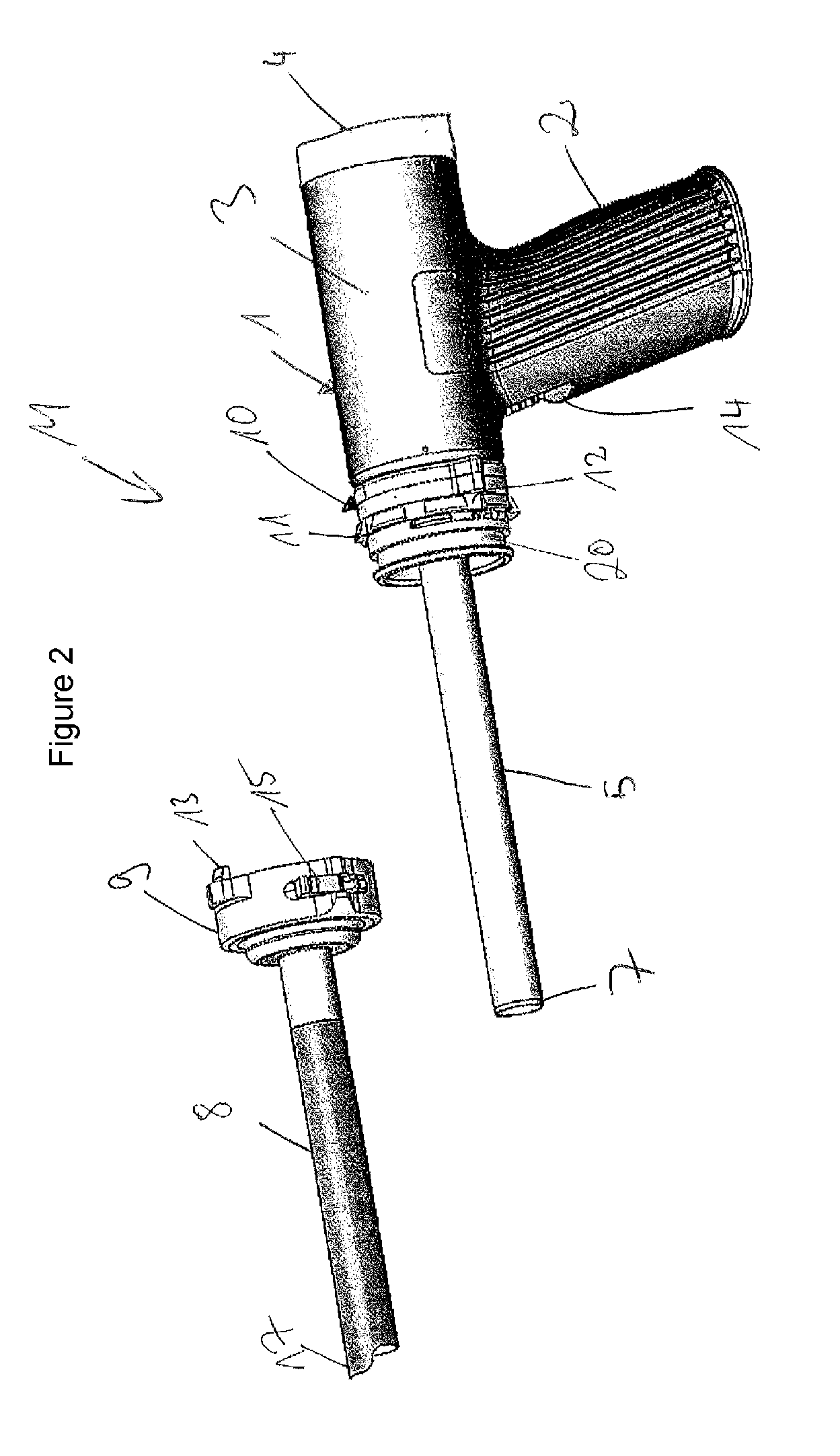
[0066]FIG. 1 shows a connecting element according to the invention for a morcellator M. The connecting element consists of a connecting ring 9 and a connecting piece 10. In this exemplary embodiment, the connecting ring 9 is part of a sleeve 8 whereas the connecting piece is part of a hand module 1. The morcellator M consists here of the hand module 1, a cutting tube 5 and the sleeve 8. The connecting ring 9 can be clipped onto the connecting piece. This means that, as a rule, the internal circumference of the connecting ring is larger than the external circumference of the connecting piece 10.

[0067]In addition, a flange-mounted ring 11 which is formed as part of the connecting piece 9 can be seen. The flange-mounted ring 11 has various recesses 12. Said various recesses 12 are distributed here over the entire circumference of the flange-mounted ring 11. Furthermore, a flange cam 13 which is formed as part of the connecting ring 9 can be seen. FIG. 1 furthermore shows that the cutti...


PUM


Abstract

A connecting element for a morcellator (M). The morcellator (M) has a hand module (1), a cutting tube (5) and a sleeve (8), the hand module (1) comprising a connecting piece (10) and the sleeve (8) comprising a connecting ring (9). The connecting ring (9) can be clipped onto the connecting piece (10).

Description

BACKGROUND OF THE INVENTION[0001]The invention relates to a connection for a morcellator and to a protective sleeve for a medical instrument.[0002]Various connections for morcellators are known and customary in the prior art. The invention can be used wherever a rotating cutting tube, which is configured in particular as a cutting tube, is used to carry out an activity in the body of a living being. Medical instruments of this type are currently used especially in endoscopic interventions. They are used to remove relatively large portions of tissue.[0003]The morcellator especially has, as cutting tube, a cutting tube which has a cutting edge at the distal end. Said cutting tube is introduced into the body, for example, through an endoscope and is then rotated. By this means, the cutting edge removes portions of tissue which are then removed from the body through the cutting tube itself. For this purpose, the tissue part can be sucked off or else also removed by a further medical ins...

Claims


Application Information

Patent Timeline
IPC IPC(8): A61B17/32A61B17/34
CPCA61B17/32002A61B17/3496A61B2017/00455A61B2019/481A61B2017/00477A61B2017/320024A61B2017/0046A61B2090/08021
Inventor TRONDLE, KARLHEINZ
Owner TROKAMED
Learn More