Production method for phase shift film, and production method for circular polarizing plate

Inactive Publication Date: 2016-04-07
NITTO DENKO CORP
View PDF3 Cites 4 Cited by
  • Summary
  • Abstract
  • Description
  • Claims
  • Application Information

AI Technical Summary

Benefits of technology

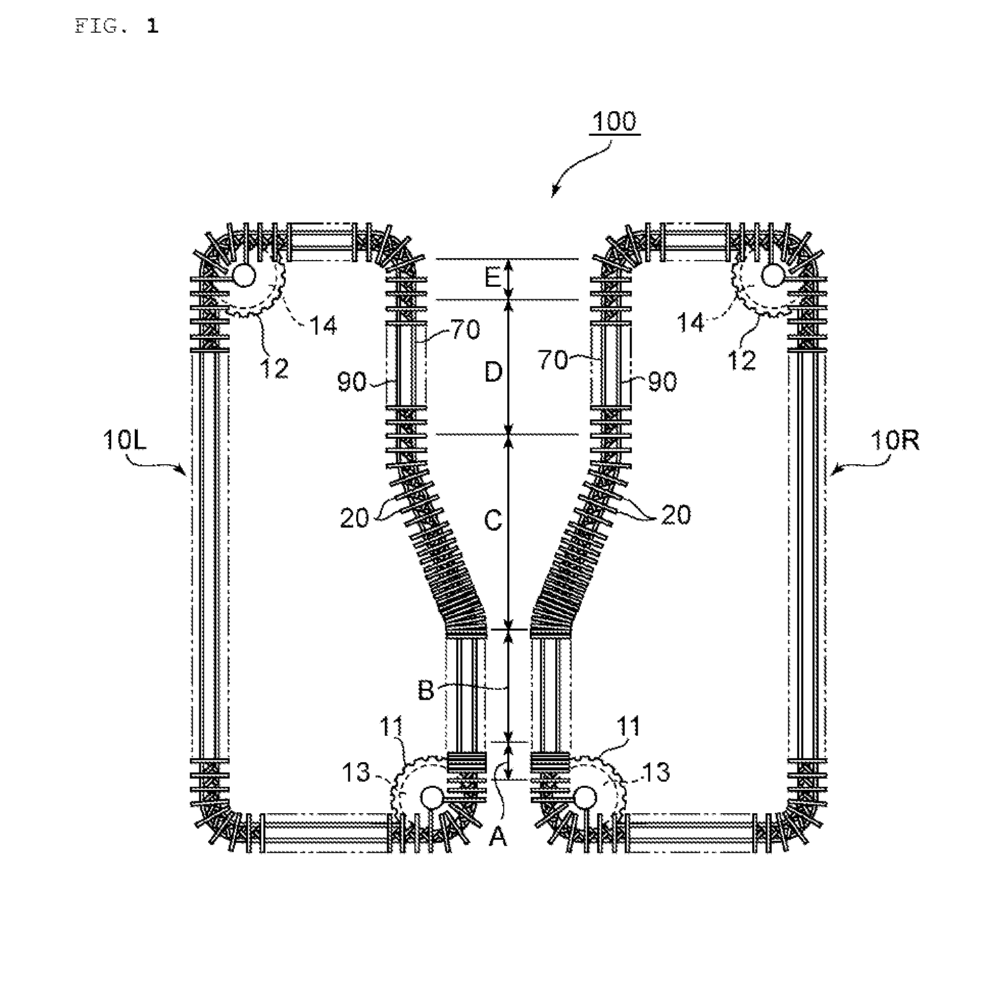
[0013]According to the embodiments of the present invention, the oblique stretching is performed by reducing the clip pitch of each of the left and right clips to a predetermined pitch under a state in which positions at which the clip pitches of the clips start to reduce are set to different positions in the longitudinal direction, whereby the retardation film suppressed in biaxiality, having a small Nz c

Problems solved by technology

The use of such retardation film in an image display apparatus having a high reflectance involves a problem

Method used


Image

  • Production method for phase shift film, and production method for circular polarizing plate
  • Production method for phase shift film, and production method for circular polarizing plate
  • Production method for phase shift film, and production method for circular polarizing plate

Examples


Example

Example 1

Production of Polycarbonate Resin Film

[0079]Polymerization was performed with a batch polymerization apparatus formed of two vertical reactors each including a stirring blade and a reflux condenser controlled to 100° C. 9,9-[4-(2-Hydroxyethoxy)phenyl]fluorene (BHEPF), isosorbide (ISB), diethylene glycol (DEG), diphenyl carbonate (DPC), and magnesium acetate tetrahydrate were loaded at a molar ratio “BHEPF / ISB / DEG / DPC / magnesium acetate” of 0.348 / 0.490 / 0.162 / 1.005 / 1.00×10⁻⁵. After a first reactor had been sufficiently purged with nitrogen (oxygen concentration: 0.0005 vol % to 0.001 vol %), the inside of the reactor was warmed with a heating medium, and when a temperature in the reactor reached 100° C., stirring was started. 40 Minutes after the start of the temperature increase, the internal temperature was caused to reach 220° C. and the reactor was controlled so as to hold the temperature, and at the same time, a pressure reduction was started. 90 Minutes after the tempera...

Example

Example 2

[0084]A retardation film was obtained in the same manner as in Example 1 except that: the thickness of the polycarbonate resin film before the stretching was set to 175 μm; and the stretching ratio in the lateral direction was set to 2.5 times. The resultant retardation film was subjected to the same evaluations as those of Example 1. The results are shown in Table 1.

Example

Example 3

[0085]A retardation film was obtained in the same manner as in Example 1 except that: the clip pitches of the left and right clips in the preheating zone (that is, before the oblique stretching) were set to 250 mm; and the clip pitches of the left and right clips after the oblique stretching were set to 175 mm. The clip pitch change ratio before and after the oblique stretching was 0.70. The resultant retardation film was subjected to the same evaluations as those of Example 1. The results are shown in Table 1.


PUM

PropertyMeasurementUnit
Lengthaaaaaaaaaa
Ratioaaaaaaaaaa

Abstract

Provided is a method capable of producing a retardation film suppressed in biaxiality, having a small Nz coefficient, and having a slow axis in an oblique direction with high production efficiency. The production method for a retardation film of the present invention includes: holding left and right side edge portions of a film to be stretched with left and right variable pitch-type clips configured to have clip pitches changing in a longitudinal direction, respectively; preheating the film; reducing, under a state in which a position at which the clip pitch of the clips on one side out of the left and right clips starts to reduce and a position at which the clip pitch of the clips on another side starts to reduce are set to different positions in the longitudinal direction, the clip pitch of each of the clips to a predetermined pitch to subject the film to oblique stretching; and releasing the clips holding the film.

Description

TECHNICAL FIELD[0001]The present invention relates to a production method for a retardation film and a production method for a circularly polarizing plate.BACKGROUND ART[0002]A circularly polarizing plate has been used in an image display apparatus such as a liquid crystal display apparatus (LCD) or an organic electroluminescence display apparatus (OLED) for the purposes of improving its display characteristics and preventing reflection. The circularly polarizing plate is typically obtained by laminating a polarizer and a retardation film (typically a λ / 4 plate) so that the absorption axis of the polarizer and the slow axis of the retardation film may form an angle of 45°. Heretofore, the retardation film has been typically produced by performing uniaxial stretching or biaxial stretching in a longitudinal direction and / or a lateral direction, and hence its slow axis is expressed in the lateral direction (widthwise direction) or longitudinal direction (lengthwise direction) of a raw ...

Claims


Application Information

Patent Timeline
IPC IPC(8): B29C55/04G02B5/30B29D11/00
CPCB29C55/045B29D11/00644G02B5/3083B29K2995/0034B29K2069/00B29K2029/14B29K2105/256B29C55/04B29C55/165B29C55/16G02B5/3041G02B1/04
Inventor SHIMIZU, TAKASHIHIRATA, SATOSHIKONDO, SEIJIMURAKAMI, NAO
Owner NITTO DENKO CORP
Why Eureka
Try Eureka