Connection Point For Metal Structure

a connection point and metal structure technology, applied in the field of connecting points of metal structures, can solve the problems of lack of flexibility in the assembly, inability to be separated to be adequately rearranged or positioned, and the type of connection stability problems

Inactive Publication Date: 2016-04-07
IND METALICAS ANRO
View PDF6 Cites 9 Cited by
  • Summary
  • Abstract
  • Description
  • Claims
  • Application Information

AI Technical Summary

Problems solved by technology

In general, these types of connections have connection stability problems, at least unless the connection is secured using the definitive methods adopted in each case, due to which it is necessary to execute the definitive fixation of the el

Method used


Image

  • Connection Point For Metal Structure
  • Connection Point For Metal Structure
  • Connection Point For Metal Structure

Examples


Embodiment Construction

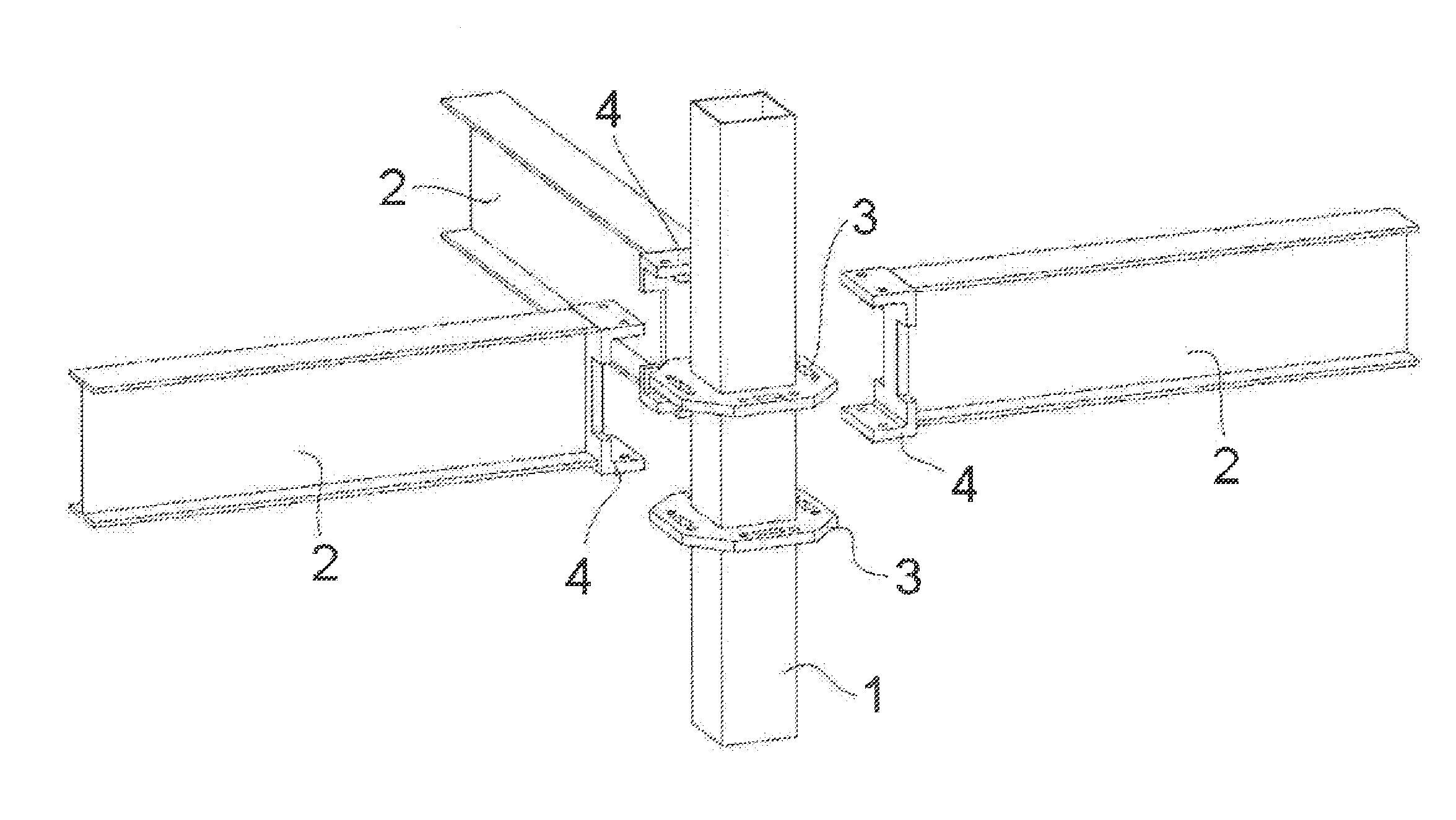
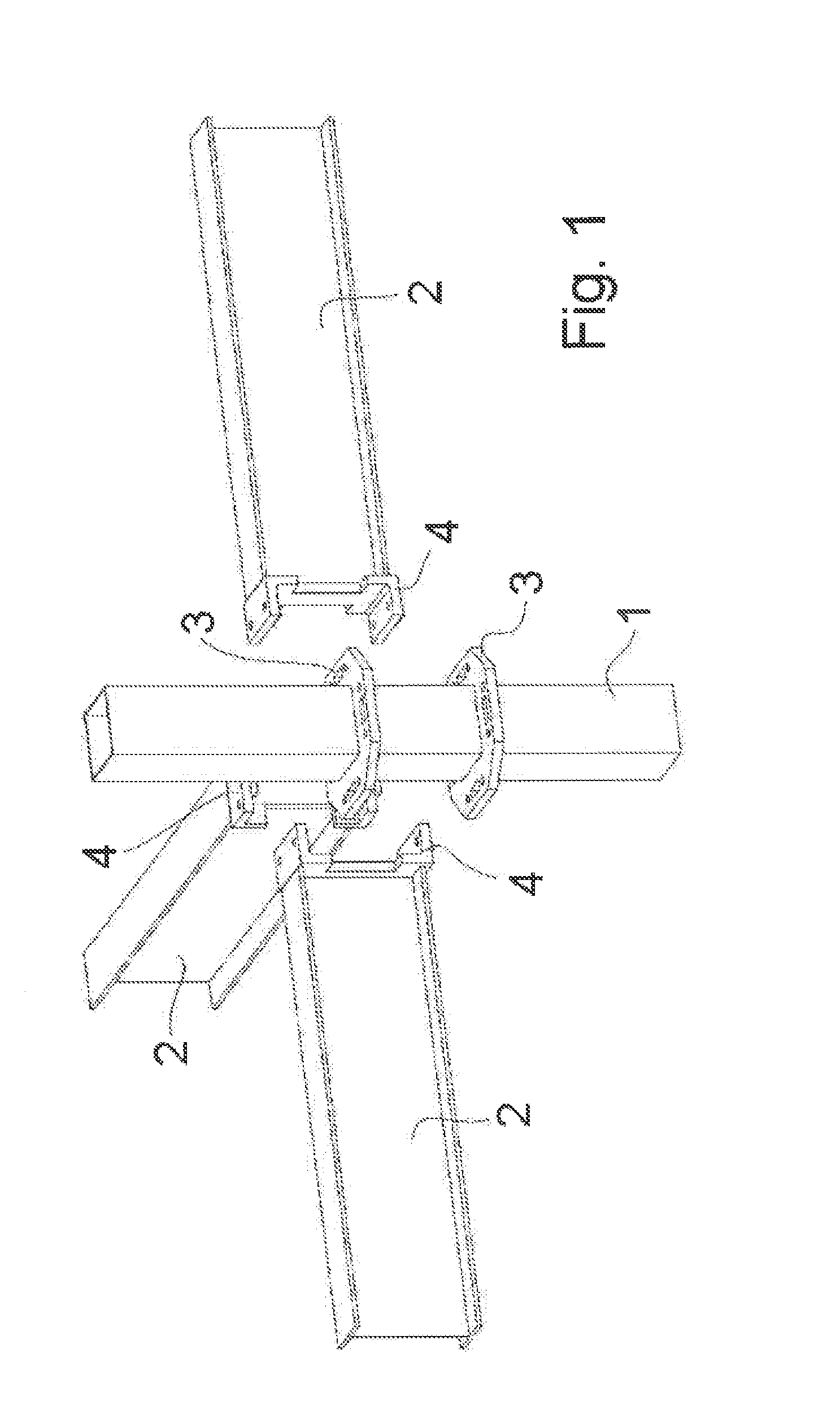
[0004]The invention proposes to resolve this question, for which on the one hand it is possible to execute a fast and effective pre-assembly of the structure and, once it has the adequate configuration and all its elements are in the definitive position, the nodes are definitively fixed. This fixation is preferably performed by means of screws, although it may also be the object of riveted joints.

[0005]The pre-assembly of the constituent parts of a node can only be executed in a stable position, wherein the parts adopt well-defined and geometric positions which therefore do not require subsequent adjustments. For example, on assembling several beams on a prop disposed at 90°, the interlocking thereof is necessarily a right angle, i.e. perpendicular to the sides of the prop and it is only possible with a minimum tolerance margin.

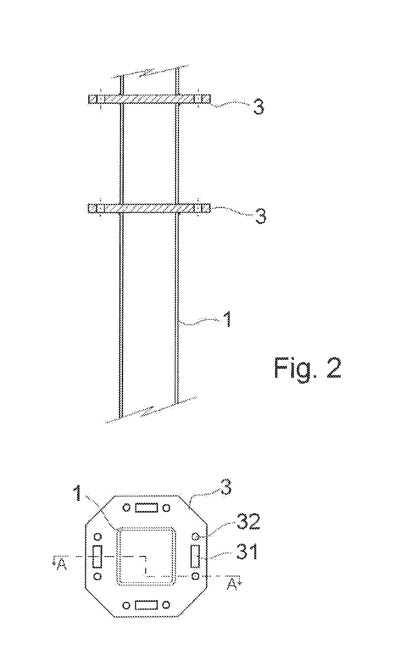
[0006]This node is composed of two differentiated elements: a post or pillar having coupling means for the relevant beams at an adequate height or heights, i...


PUM


Abstract

A connecting node for metallic structures, specifically for structures based on props or pillars (1) wherewith cross beams (2) are associated, wherein said pillars (1) incorporate rosettes (3) separated by a predetermined distance, each of which having a polygonal window (31) and at least one circular hole (32); while the beams (2) include on their edges a fork (4) having a stub (41) with a polygonal configuration that projects from the lower side and has a configuration equivalent to the window (31) and at least one hole (42) in correspondence with the hole (32) of the rosettes (3); the foregoing in anticipation that a fork (4) will be fitted into a pair of rosettes (3) without possibility of sideways movement of the beam (2) and, once the structure is assembled, that it will be immobilised by means of at least one screw (6) which, passing through holes (32) and (42), establishes the definitive connection.

Description

OBJECT OF THE INVENTION[0001]The objective of the present invention is a semi-rigid connecting node for metallic structures which allows connection between beams and pillars, the main application of which is the construction of multi-storey car parks, although it may be destined for the construction of any other metallic structure or construction integrating a metallic structure. This node has a high degree of prefabrication in that its components are manufactured and assembled in situ in embedding and screwing operations which make it possible to improve safety in construction and reduce work execution and completion costs and timeframes.BACKGROUND OF THE INVENTION[0002]Structures are known to exist, particularly for scaffolds wherein the structure is formed by props or pillars wherewith cross beams are associated, wherein said pillars include rosettes for fixing the beams, while these include fixing forks at the ends of their spans for fixing to said rosettes, envisaging the exist...

Claims


Application Information

Patent Timeline
IPC IPC(8): E04B1/19E04B1/21E04B1/24E04C3/02
CPCE04B1/1903E04C3/02E04B1/215E04B1/2403E04B2001/2418E04B2001/2421E04B2001/2457E04B2001/246E04B2001/2415E04B2001/2406E04B2001/2454E04B1/24
Inventor MARQUINA, AMALIO BRIONES
Owner IND METALICAS ANRO
Why Eureka
Try Eureka