
Ceramic electronic component

a technology of ceramic electronic components and components, applied in the direction of fixed capacitor details, generators/motors, fixed capacitors, etc., can solve problems such as crack generation, and achieve the effect of preventing crack generation and reducing residual stress

Active Publication Date: 2016-04-07
MURATA MFG CO LTD
View PDF13 Cites 35 Cited by
  • Summary
  • Abstract
  • Description
  • Claims
  • Application Information

AI Technical Summary

Benefits of technology

This patent provides a ceramic electronic component and a method for making it that prevents the component from cracking due to high levels of residual stress. The method reduces the chances of cracks forming in the component caused by a combination of residual stress and external stress.

Problems solved by technology

When the multilayer ceramic capacitor mounted on a circuit board is subjected to an external force, a combination of residual stress and external stress may be concentrically loaded on portions of the laminated body in contact with ends of the sintered metal layers of the external electrodes on the side opposed to the circuit board, thereby resulting in crack generation.

Method used


Image

  • Ceramic electronic component
  • Ceramic electronic component
  • Ceramic electronic component

Examples


experimental examples

[0139]In the experimental examples, prepared were three types of ceramic electronic components according to Comparative Examples 1 and 2 and Example 1. First, conditions (designed values) common to the three types of ceramic electronic components will be described.

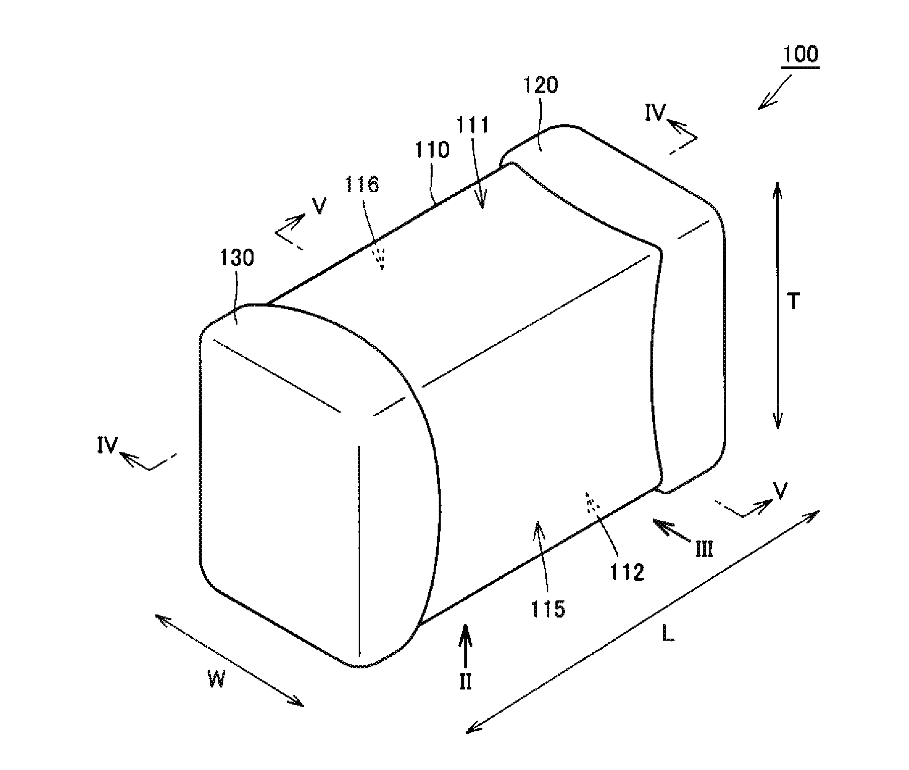
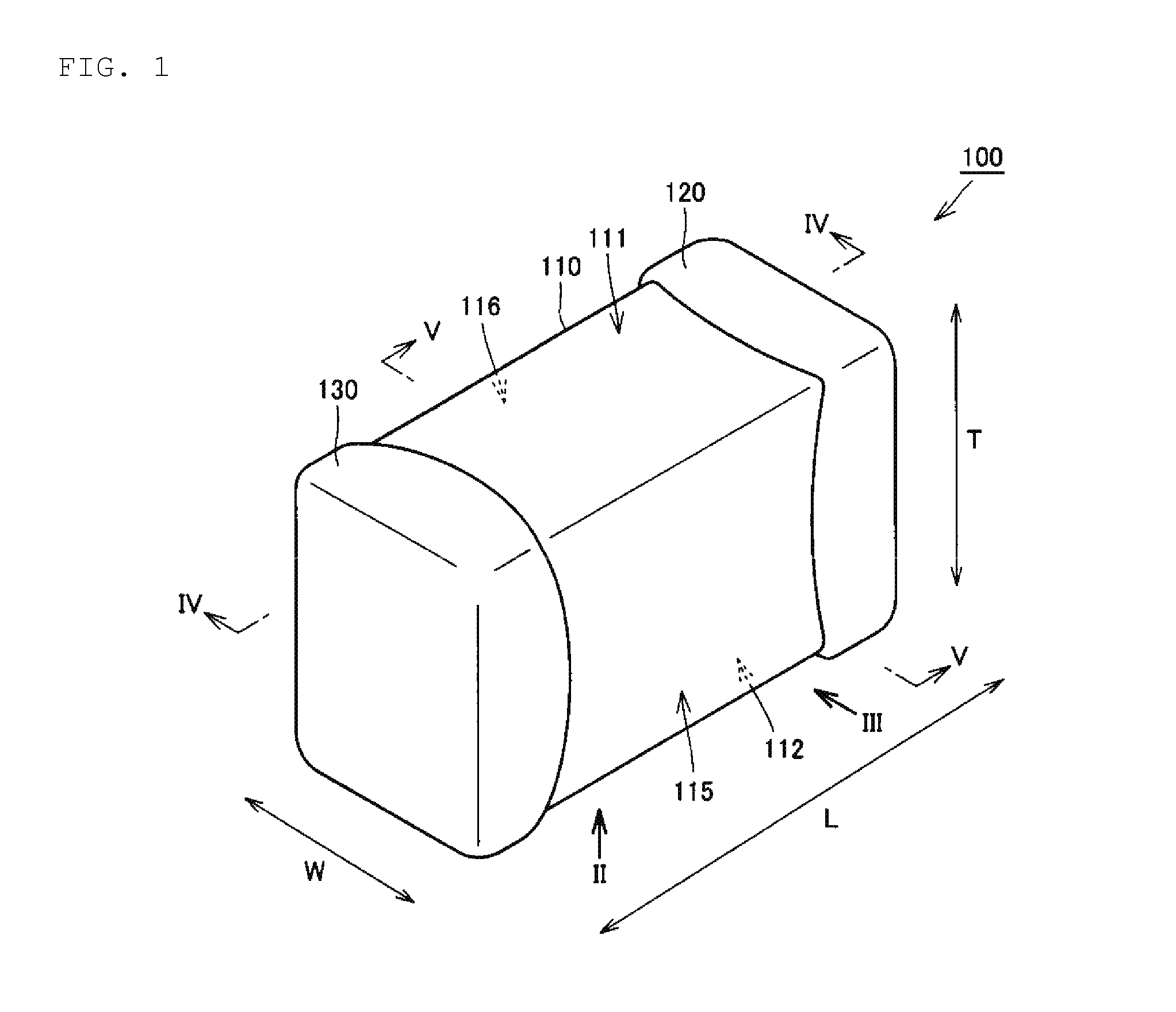
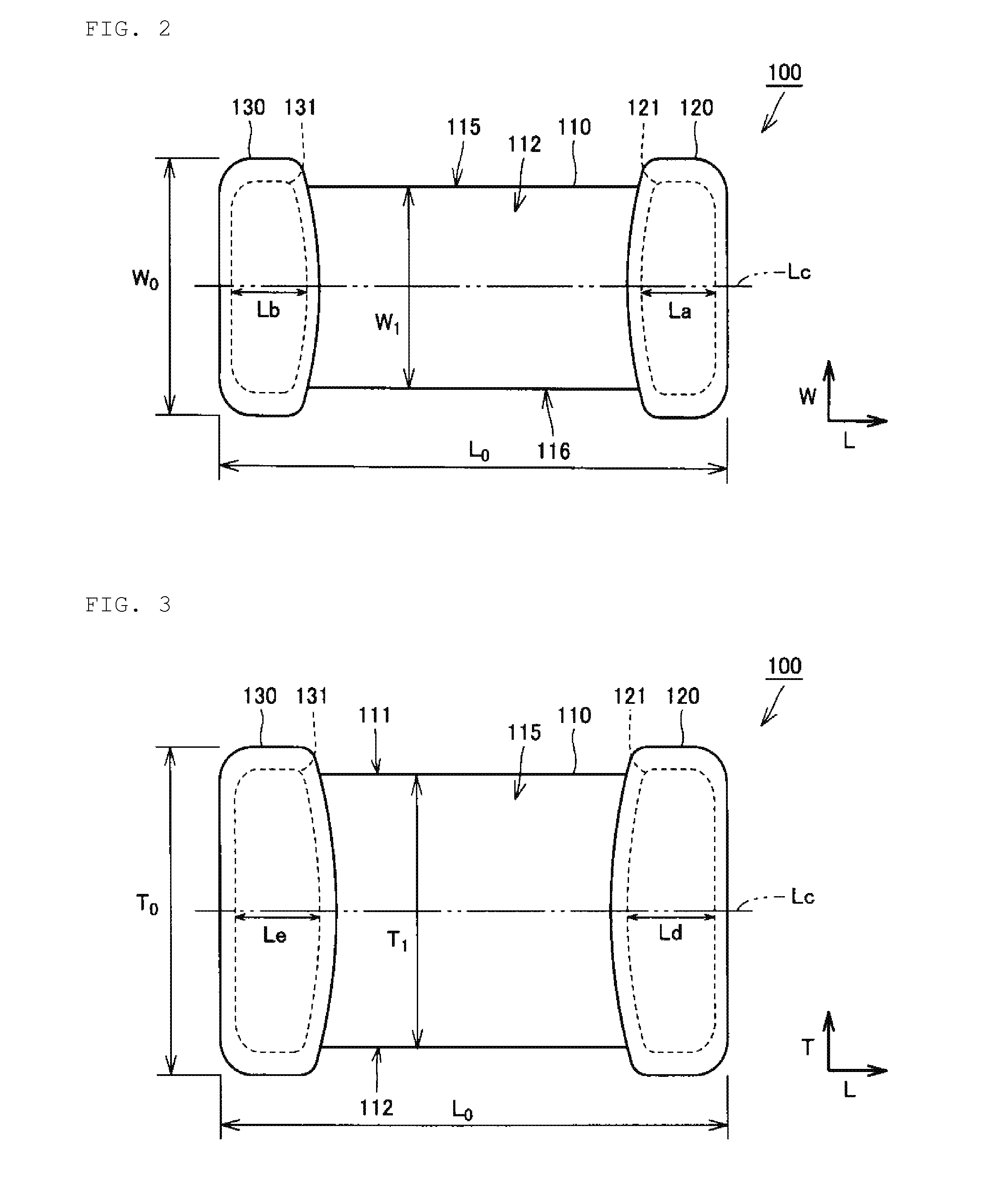
[0140]The external dimensions of the ceramic electronic components were adjusted to 1.1 mm in length L0, 0.6 mm in width W0, and 0.9 mm in thickness T0. The first outer layer portion and the second outer layer portion were each adjusted to 40 μm in thickness. The thickness of the sintered metal layer was adjusted to 5 μm on the first and second principal surfaces 111, 112 and on the first and second side surfaces 115, 116, and to 10 μm on the first and second end surfaces 113, 114. The thickness of the conductive resin layer was adjusted to 10 μm on the first and second principal surfaces 111, 112 and on the first and second side surfaces 115, 116, and to 20 μm on the first and second end surfaces 113, 114. The thickness o...


PUM

PropertyMeasurementUnit
lengthaaaaaaaaaa
thicknessaaaaaaaaaa
thicknessaaaaaaaaaa

Abstract

A ceramic electronic component includes a laminated body including ceramic layers and conductor layers stacked alternately; and first and second external electrodes provided on portions of the laminated body. Each of the first and second external electrodes includes a sintered metal layer provided on the laminated body, a conductive resin layer covering the sintered metal layer, and a plated layer covering the conductive resin layer. The maximum length of the sintered metal layer provided on the second principal surface is shorter than the maximum length of the sintered metal layer provided on each of the first and second side surfaces.

Description

BACKGROUND OF THE INVENTION[0001]1. Field of the Invention[0002]The present invention relates to a ceramic electronic component.[0003]2. Description of the Related Art[0004]In recent years, ceramic electronic components typified by multilayer ceramic capacitors have been used under more inhospitable environments than ever before.[0005]For example, electronic components for use in mobile devices such as cellular phones and portable music player are required to withstand dropping impacts. Specifically, the electronic components are required to keep from dropping from mounting boards and keep themselves from being cracked, when the electronic components are subjected to dropping impacts.[0006]Furthermore, electronic components for use in in-car devices such as an ECU (Engine Control Unit) are required to withstand thermal cycle impacts. Specifically, the electronic components are required to keep solder used to mount the components and the components themselves from being cracked when ...

Claims


Application Information

Patent Timeline
Patent Type & Authority Applications(United States)
IPC IPC(8): H01G4/008H01F27/28H01G4/12H01G4/30H01G4/012H01L41/083H01C7/00
CPCH01G4/008H01L41/083H01F27/2804H01C7/008H01F2027/2809H01G4/012H01G4/1227H01G4/1236H01G4/30H01G4/0085H01F17/0013H01F27/292H10N30/50H10N30/067H10N30/872H10N30/8554H01C1/14H01F27/29H01G4/12H01G4/248
Inventor KUROKAWA, KAZUKIADACHI, HIROBUMI
Owner MURATA MFG CO LTD
Learn More