
Ear-mounted device

a technology of ear hooks and ear clips, which is applied in the direction of umbrellas, travel objects, etc., can solve the problems of affecting the use of traditional glasses, ear hook devices are not suitable for use, and the ear hook solution suffers

Inactive Publication Date: 2016-04-14
FREEBIT AS
View PDF39 Cites 21 Cited by
  • Summary
  • Abstract
  • Description
  • Claims
  • Application Information

AI Technical Summary

Benefits of technology

The patent text describes a device that can be attached to the ear to carry a load. The device has a rotational stabilizer to make it stabler. The load-bearing ear unit is designed to be stable and secure in the ear, which provides a comfortable and safe mount for various optical devices. This invention allows for the safe and secure use of optical devices in various applications such as medical procedures and sports equipment.

Problems solved by technology

However ear hook solutions suffer from several problems such as instability due to rotational momentum caused by the relatively long arm.
Also a counterbalance will not improve matter regarding the stability in following head movement.
Moreover an ear hook device will interfere with use of traditional glasses.
Stabilisation using the nose will also interfere with use of glasses and can also be uncomfortable particularly for heavier devices such as glasses, VR-equipment and the like.
However to provide stability the headband has to be relatively tight and thus less comfortable.
Such a positioning is also far from unobtrusive.
The positioning for devices such as light sources are also problematic since the illumination is close to co-axial with the eyes of the wearer since illumination strongly reduces shadowing effects and contours resulting in flat images or “whiteout”.
The presence of a counterbalance also increases weight and discomfort.

Method used


Image

  • Ear-mounted device
  • Ear-mounted device
  • Ear-mounted device

Examples


Embodiment Construction

[0007]It is therefore an object of this disclosure to provide new and improved methodologies and designs to correct the shortcomings of the aforementioned ear-mounting devices.

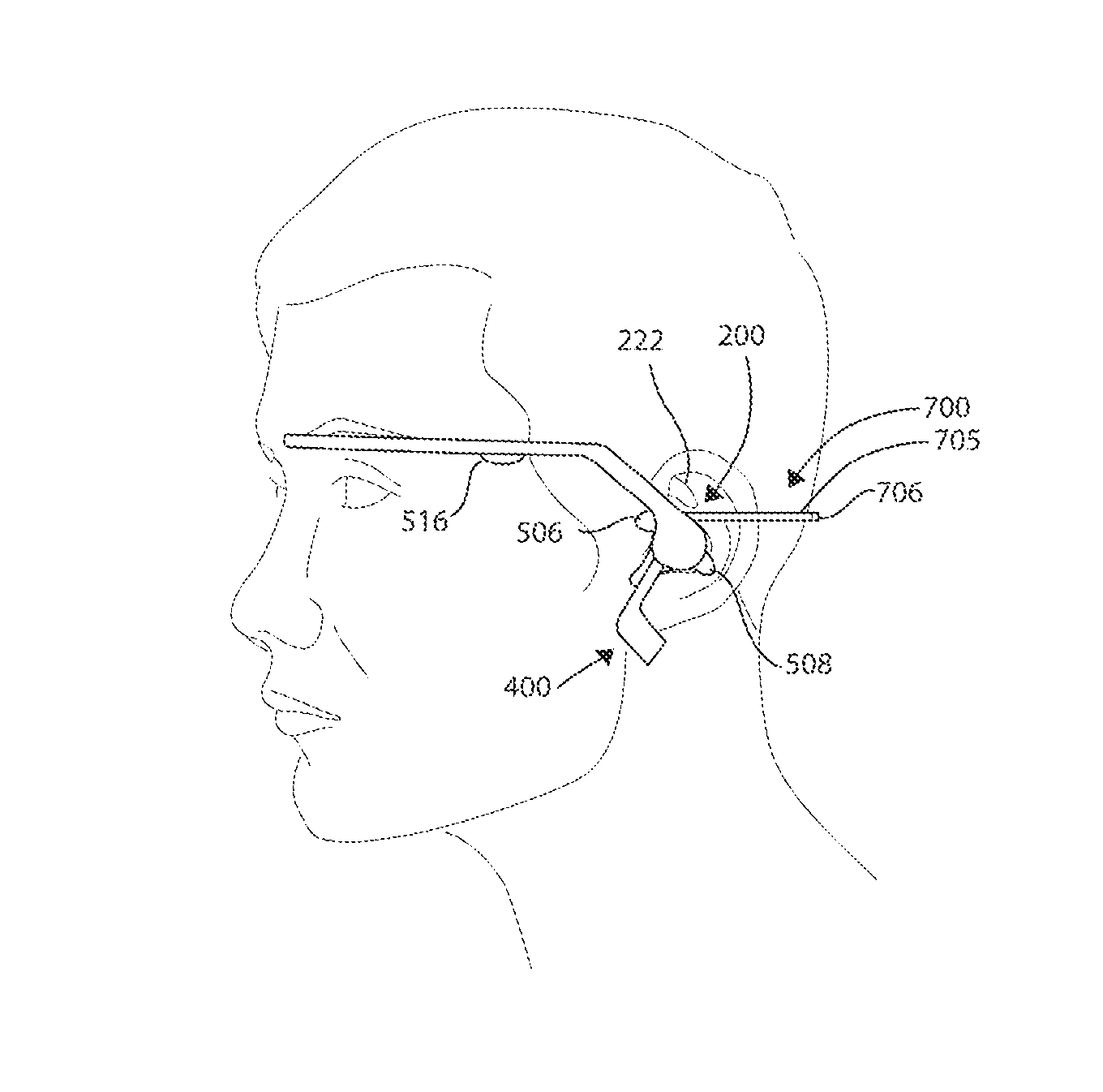
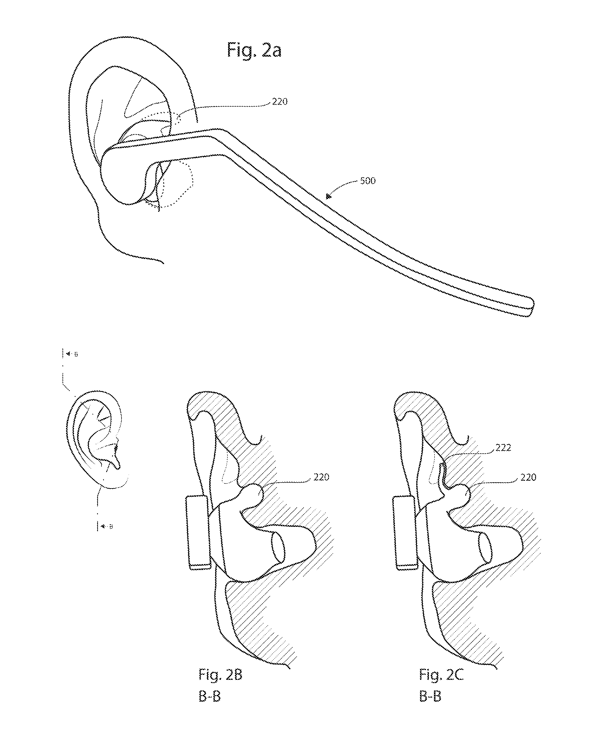
[0008]Particularly, in accordance with this disclosure, there is provided, in one embodiment, a load bearing ear unit comprising an anchor for stable attachment in an ear, and a member extending from the anchor, wherein the anchor comprises a rotational stabiliser thereby stabilizing the member.

[0009]In another embodiment, the anchor further comprises a housing unit forming an attachment connecting the member to the anchor.

[0010]In yet another embodiment, the rotational stabiliser is adapted to stabilize the member in the sagittal plane.

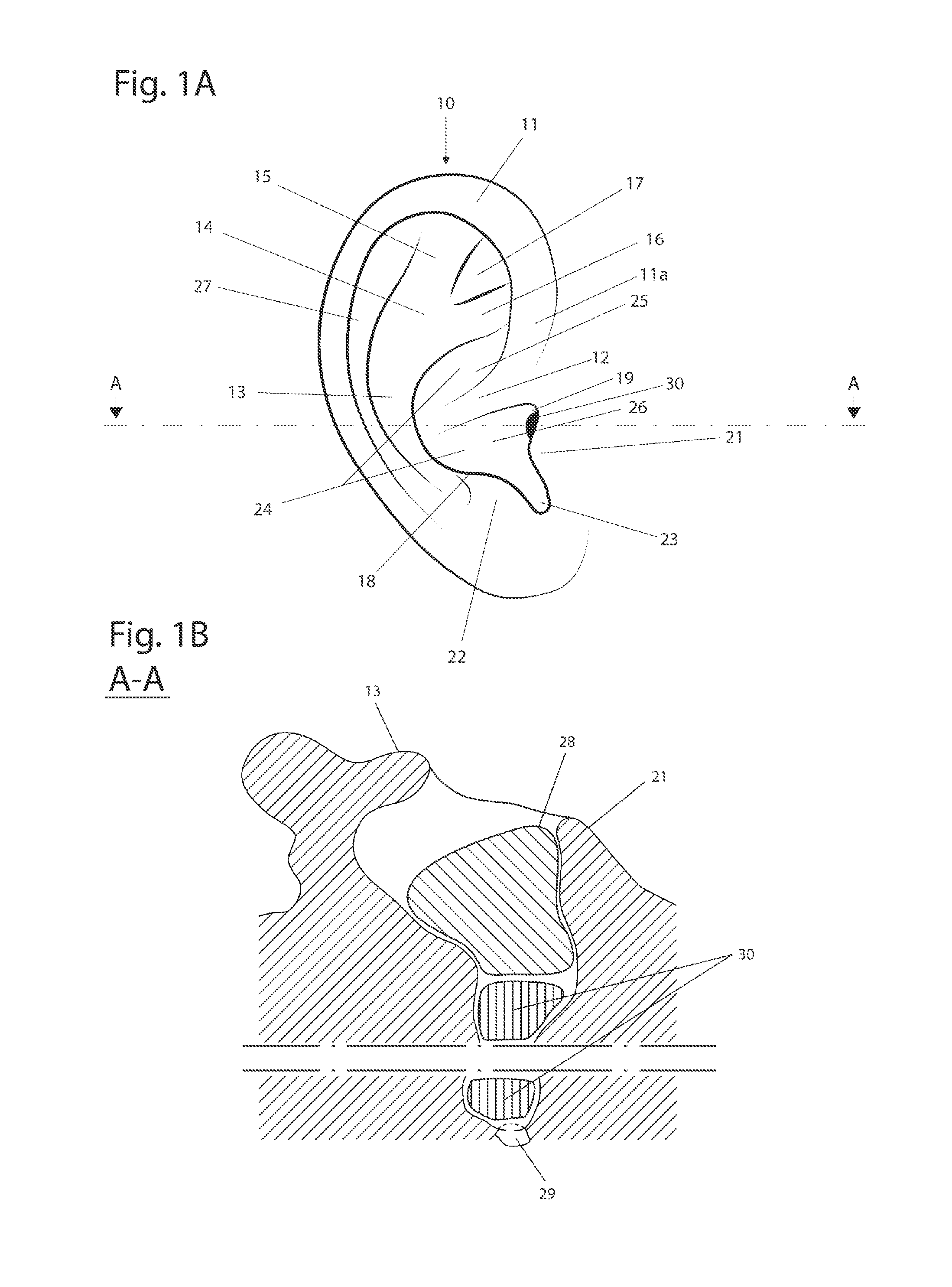
[0011]In a further embodiment, the anchor comprises an arm adapted as a decremental curve corresponding to the antihelix of the ear. The decremental curve falls along an inner part of the antihelix and is partly positioned under the antitragus.

[0012]In another embodiment, the r...


PUM


Abstract

Ear-mounted apparatus are provided for secure and comfortable load bearing in support of optical, biosensor, and mobile communication functionalities. In particular, a load-bearing ear unit is provided which includes an anchor for stable attachment in an ear and a member extending from the anchor. The member has therein a rotational stabiliser adapted to provide stability in relevant planes for secure ear mounting. Also provided is an ear-mounted optical device, comprising the load-bearing ear unit and one of a camera, a light source, a virtual reality device, a IrDA-device, and a photo diode. Further provided is an ear-mounted wearable device, comprising the load-bearing ear unit and one or more biosensors. A particular such wearable device is an ear-mounted EAG device.

Description

BACKGROUND OF THE DISCLOSURE[0001]The present disclosure relates in general to ear-mounted devices. Specifically, the present disclosure relates to apparatus for removable ear attachment to optical devices, head-mounted or head-sensing devices. More specifically, a load-bearing ear unit for secure and comfortable attachment of a forward extending member is provided. Also provided in various embodiments are ear-mounted camera, flash lights, Virtual Reality (VR) device, Infrared Data Association (IrDA) device, and Electroencephalography (EEG) device incorporated therein the load-bearing ear unit of this disclosure.[0002]Various forward extending head mounted devices are well known, such as glasses and head attached flash lights.[0003]Many solutions use an ear hook attachment wherein a member is placed between the pinna of the ear and the skull, preferably with a downward extending hook anterior to the ear. This is the typical case for glasses. References should also be made to U.S. Pa...

Claims


Application Information

Patent Timeline
Patent Type & Authority Applications(United States)
IPC IPC(8): A45F5/00
CPCA45F5/00A45F2200/0516A45F2200/0533A45F2200/0541
Inventor SANDANGER, VIDAR
Owner FREEBIT AS
Learn More