Tensioning rail with wear protection element

a technology of wear protection element and tensioning rail, which is applied in the direction of belt/chain/gearring, mechanical equipment, belts, etc., can solve the problems of failure of tensioning rail, and achieve the effect of reliable tensioning of chain drive and easy construction and mounting

Active Publication Date: 2016-04-14
IWIS MOTORSYSTEME GMBH & CO KG
View PDF1 Cites 2 Cited by
  • Summary
  • Abstract
  • Description
  • Claims
  • Application Information

AI Technical Summary

Benefits of technology

[0015]According to another embodiment, the wear protection element is configured as a sleeve for arrangement on the counter bearing and for contact with the support end of the spring unit. When the wear protection element is configured as a sleeve and arranged on the counter bearing, it can easily be constructed and mounted, so as to arrange the wear protection element safely and rapidly on the support end of the spring unit.
[0016]In addition, fastening means may be provided on the support end of the spring unit. Such fastening means, which, with respect to the strength and the brittleness of the spring unit, are normally configured as simple openings, projections, notches or holes, allow the wear protection element to be reliably secured to the spring unit, in particular in combination with complementary locking elements on the wear protection element.
[0017]The present invention additionally relates to a chain drive, in particular an auxiliary chain drive of an internal combustion engine, comprising a drive gear and at least one driven gear, an articulated chain wrapped around the drive gear and the at least one driven gear, and a tensioning rail according to one of the above embodiments, which contacts the articulated chain. Such a chain drive allows, even in the case of long operating times and high loads, a reliable tensioning of the chain drive, e.g. of the drive of an oil pump or of an air conditioning system, without any risk of a wear-dependent failure of the tensioning rail and, consequently, of the chain drive in its entirety.
[0018]In addition, the present invention also relates to the use of a tensioning rail, which comprises a basic body and a spring unit, for a chain drive of an internal combustion engine, the spring unit comprising a tensioning end arranged on the press-on surface of the basic body and a support end supportable on a counter bearing, and a wear protection element being provided between the support end and the counter bearing during operation. When a tensioning rail according to the present invention is used, such a separate wear protection element provided between the support end and the counter bearing allows a low-wear reliable operation of a chain drive of the type in question and simultaneously an optimization of the respective chain drive.

Problems solved by technology

Depending on the intensity and the duration of the load acting on a chain drive, significant wear, which may even cause a failure of the tensioning rail and, consequently, of the chain drive, may occur in particular in the area of contact between the spring unit and a counter bearing.

Method used


Image

  • Tensioning rail with wear protection element
  • Tensioning rail with wear protection element
  • Tensioning rail with wear protection element

Examples


Embodiment Construction

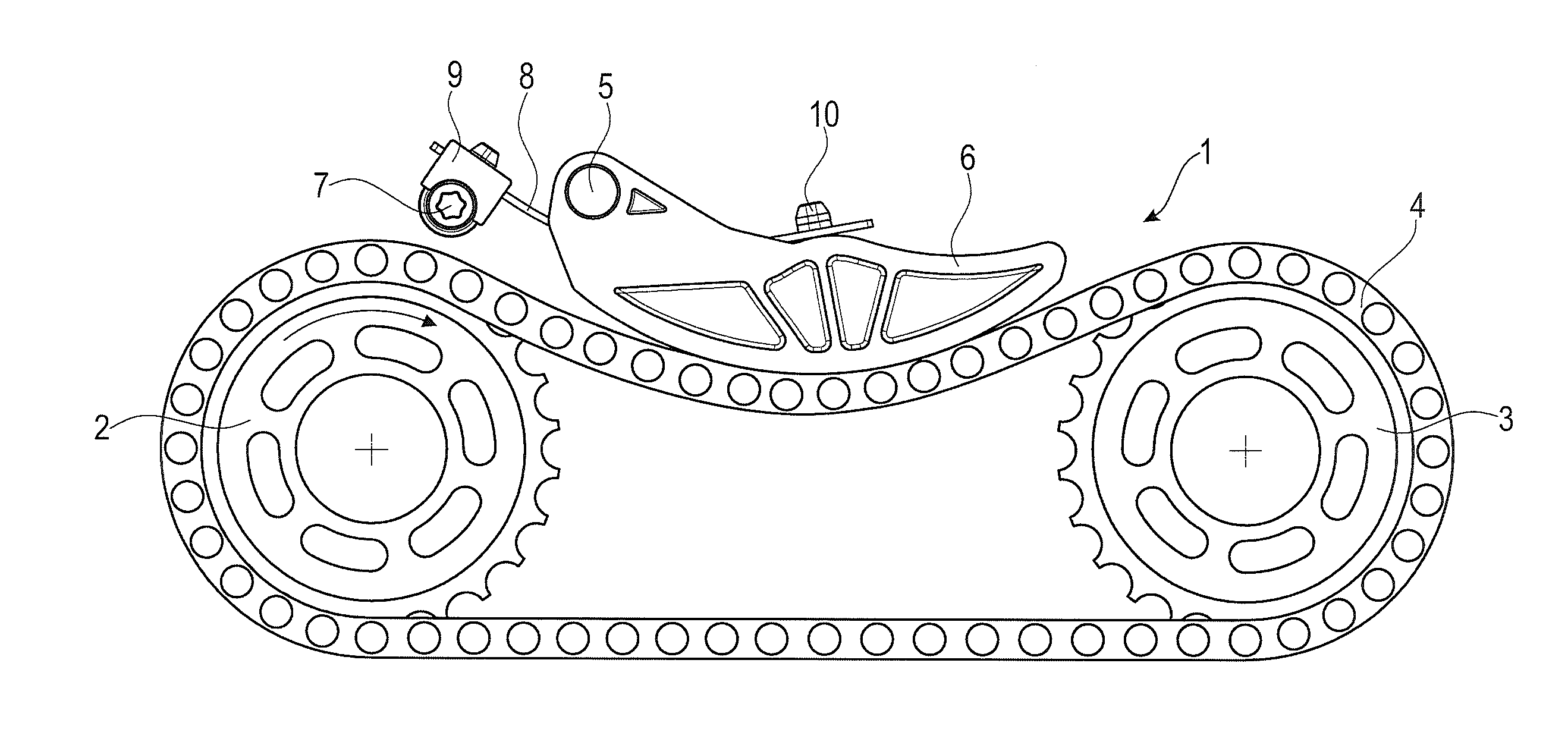
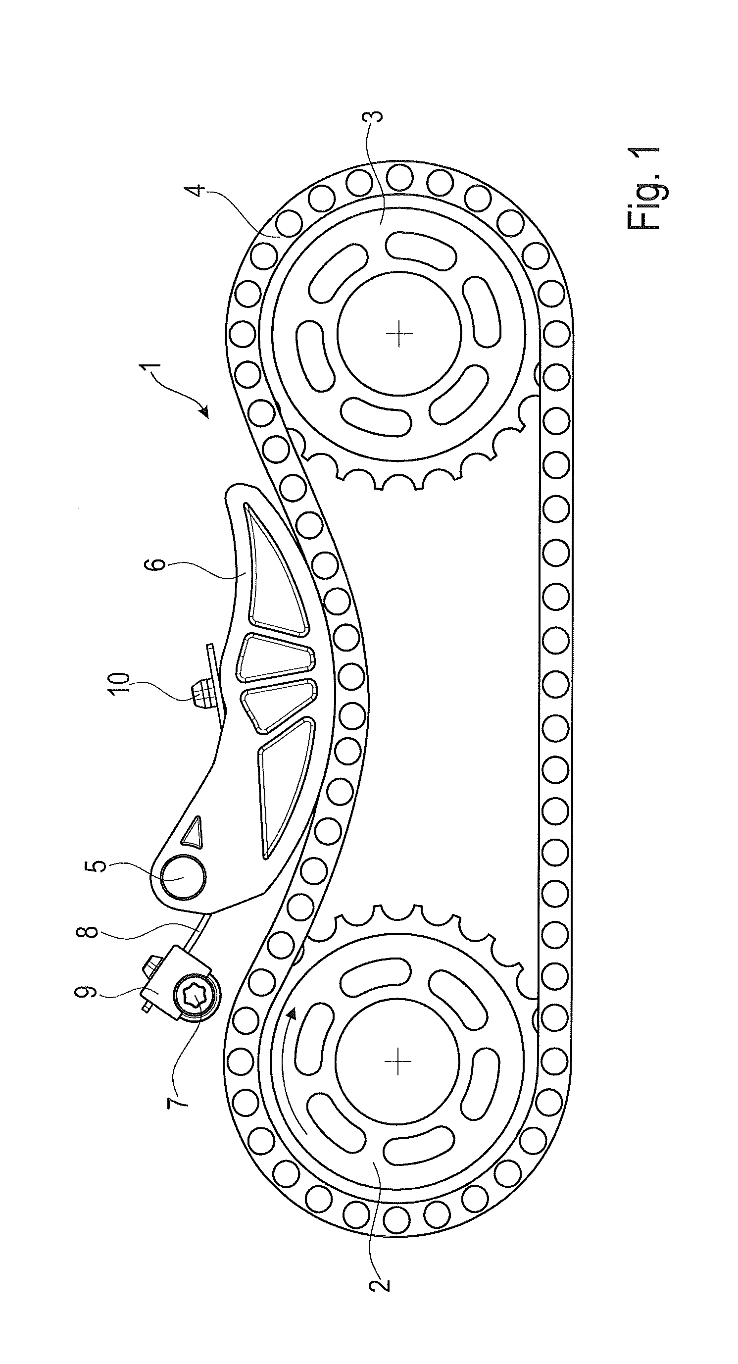
[0031]The chain drive 1 schematically shown in FIG. 1 and used for driving an auxiliary unit of an internal combustion engine, e.g. the oil pump or the compressor of the air conditioning system, comprises a driven gear 2 for connection to the auxiliary unit and a drive gear 3 for driving the chain drive 1, said drive gear 3 being coupled e.g. to the timing chain drive of the internal combustion engine. An endless drive chain 4 is wrapped around the driven gear 2 and the drive gear 3, and a tensioning rail 6 presses against the drive chain 4 in the slack span of the chain drive 1 between the driven gear 2 and the drive gear 3, said tensioning rail 6 being arranged such that it is pivotable about a bearing point 5. In the tight span of the chain drive 1, a guide rail may optionally be provided for guiding the drive chain 4. The tensioning rail 6 is pressed against the drive chain 4 by means of a spring unit 8 resting on a counter bearing 7. The counter bearing 7 and the spring unit 8 ...


PUM


Abstract

A tensioning rail for a drive chain, in particular for a chain drive of an internal combustion engine, comprises a basic body and a spring unit, the basic body including a sliding surface for contact with the drive chain and a press-on surface. The spring unit comprises a tensioning end arranged on the press-on surface and a support end supportable on a counter bearing, a wear protection element being provided, which is arranged at the support end of the spring unit. In addition, the invention relates to a chain drive including such a tensioning rail as well as to the use of such a tensioning rail for a chain drive of an internal combustion engine.

Description

CROSS-REFERENCE TO RELATED APPLICATION[0001]This application claims priority to foreign German patent application No. DE 10 2014 015 156.5, filed on Oct. 14, 2014, the disclosure of which is incorporated by reference in its entirety.FIELD OF THE INVENTION[0002]The present invention relates to a tensioning rail for a drive chain, in particular for a chain drive of an internal combustion engine, comprising a basic body and a spring unit, the basic body including a sliding surface for contact with the drive chain and a press-on surface, wherein the spring unit comprises a tensioning end arranged on the press-on surface and a support end supportable on a counter bearing. In addition, the present invention relates to a chain drive including such a tensioning rail as well as to the use of such a tensioning rail for a chain drive of an internal combustion engine.BACKGROUND[0003]Tensioning rails are used in large numbers for various applications in internal combustion engines, both for the ...

Claims


Application Information

Patent Timeline
Patent Type & Authority Applications(United States)
IPC IPC(8): F16H7/08F16H7/06
CPCF16H7/08F16H7/06F16H2007/0842F16H2007/0804F16H2007/0872F16H2007/0893
Inventor VON VOPELIUS-FELDT, PHILLIPPSTIGLMAIER, FRANZ
Owner IWIS MOTORSYSTEME GMBH & CO KG
Why Eureka
Try Eureka