Illumination device
a technology of endoscope and slit, which is applied in the field of slit device, can solve the problems of large increase in the tip diameter of the endoscop
- Summary
- Abstract
- Description
- Claims
- Application Information
AI Technical Summary
Benefits of technology
Problems solved by technology
Method used
Image
Examples
first embodiment
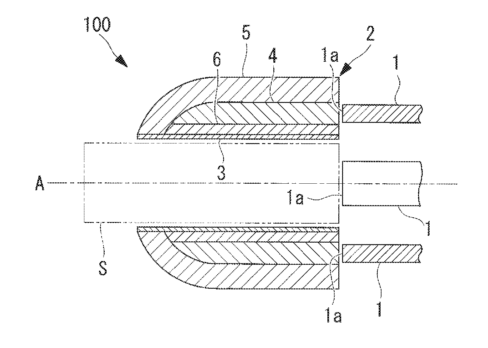
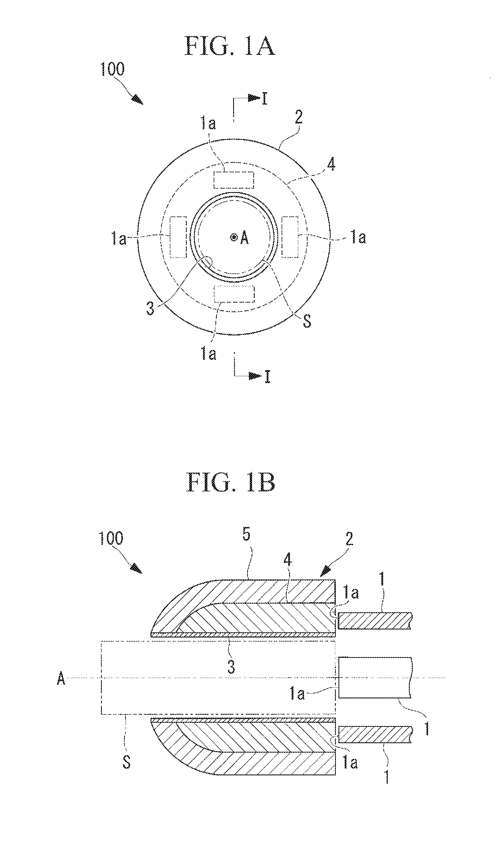
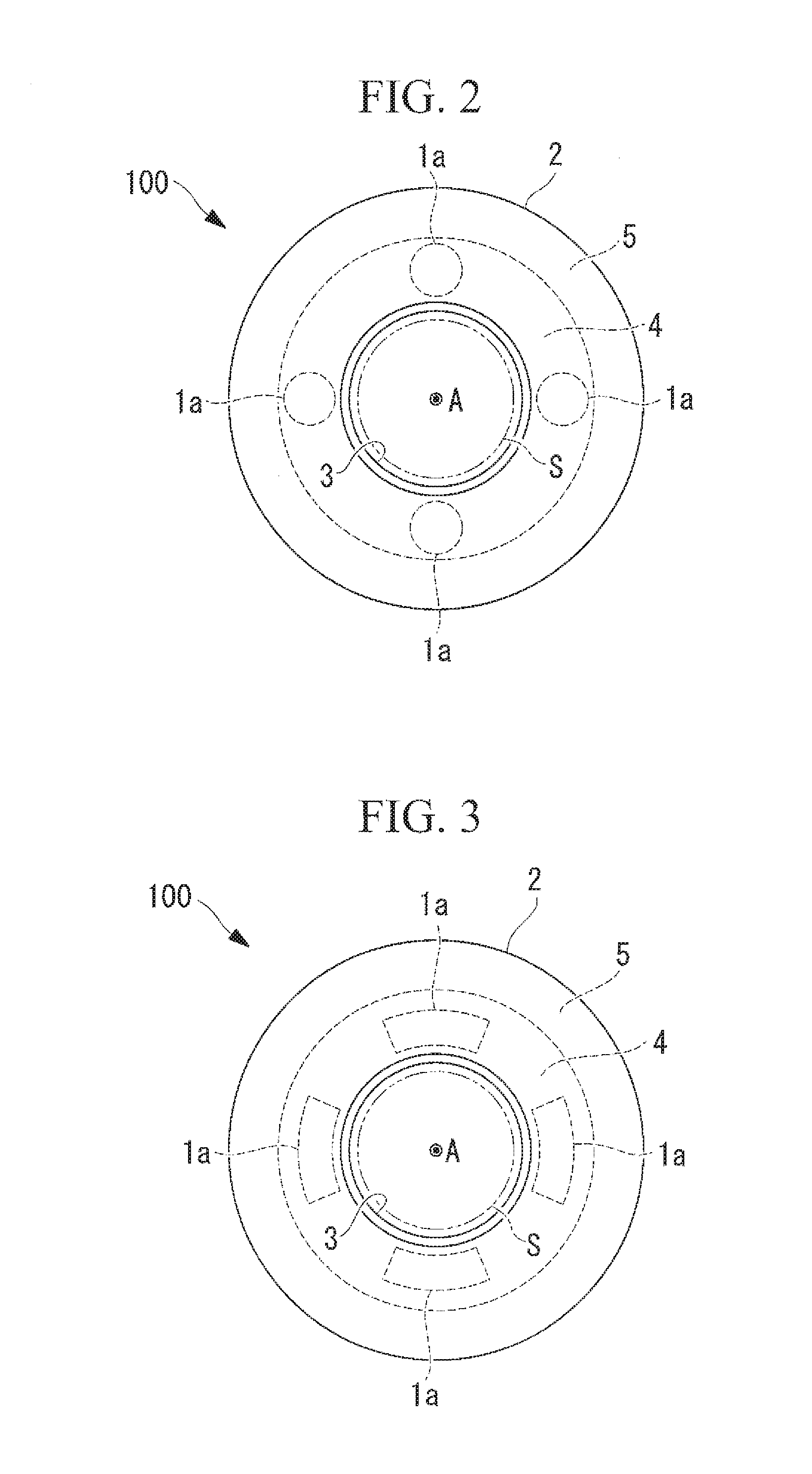
[0024]An illumination device 100 according to a first embodiment of the present invention will be described below with reference to FIGS. 1A to 6.
[0025]As shown in FIGS. 1A and 1B, the distal-end portion of the illumination device 100 according to this embodiment (i.e., a portion composed of an optical member 2 and a reflective layer 3, described later) has a cylindrical structure and is exposed to the outside so as to circumferentially surround an image-capturing optical system provided at the distal end of an endoscope. In the same figures, the space S enclosed by the two-dot chain line represents the space where the image-capturing optical system is disposed, and the axis A represents the observation optical axis of the image-capturing optical system. In particular, the illumination device 100 according to this embodiment is designed for endoscopes including image-capturing optical systems having viewing angles of 180° or more and capable of simultaneously capturing images of fie...
second embodiment
[0045]An illumination device 200 according to a second embodiment of the present invention will now be described with reference to FIGS. 7 and 8. In this embodiment, the elements that differ from those of the first embodiment described above are mainly described, whereas the same elements as in the first embodiment are labeled with the same reference signs and are not described.
[0046]As shown in FIG. 7, the illumination device 200 according to this embodiment differs from the illumination device 100 according to the first embodiment mainly in that the illumination device 200 includes an optical member 21 having an approximately C-shaped transverse cross-section formed by removing a portion extending in the circumferential direction, rather than the optical member 2 extending over the entire circumference thereof.
[0047]A cutout 21a formed by removing, in the longitudinal direction, a portion of the optical member 21 extending in the circumferential direction has an annular-sector-sha...
third embodiment
[0052]An illumination device 300 according to a third embodiment of the present invention will now be described with reference to FIGS. 9A to 10B. In this embodiment, the elements that differ from those of the first and second embodiments described above are mainly described, whereas the same elements as in the first and second embodiments are labeled with the same reference signs and are not described.
[0053]As shown in FIGS. 9A and 9B, the illumination device 300 according to this embodiment differs from the illumination devices 100 and 200 according to the first and second embodiments mainly in that the illumination device 300 includes a plurality of (in this example, four) optical members 22 arranged substantially at regular intervals in the circumferential direction centered on the observation optical axis A, rather than the cylindrical optical members 2 and 21, and that the illumination device 300 includes four units each composed of an optical member 22, a reflective layer 32,...
PUM
 Abstract
Description
Claims
Application Information
 - R&D
- Intellectual Property
- Life Sciences
- Materials
- Tech Scout
- Unparalleled Data Quality
- Higher Quality Content
- 60% Fewer Hallucinations
Browse by: Latest US Patents, China's latest patents, Technical Efficacy Thesaurus, Application Domain, Technology Topic, Popular Technical Reports.
© 2025 PatSnap. All rights reserved.Legal|Privacy policy|Modern Slavery Act Transparency Statement|Sitemap|About US| Contact US: help@patsnap.com


