High Pressure Blowout Preventer System

a technology of blowout prevention and high pressure, which is applied in the direction of program control, borehole/well accessories, instruments, etc., can solve the problems of loss of benefits to the countries who own the associated oil reserves, the oil and gas industry, and consumers, and achieve the effect of effective testing the bop stack

Active Publication Date: 2016-04-21
HYDRIL USA DISTRIBUTION LLC
View PDF3 Cites 33 Cited by
  • Summary
  • Abstract
  • Description
  • Claims
  • Application Information

AI Technical Summary

Benefits of technology

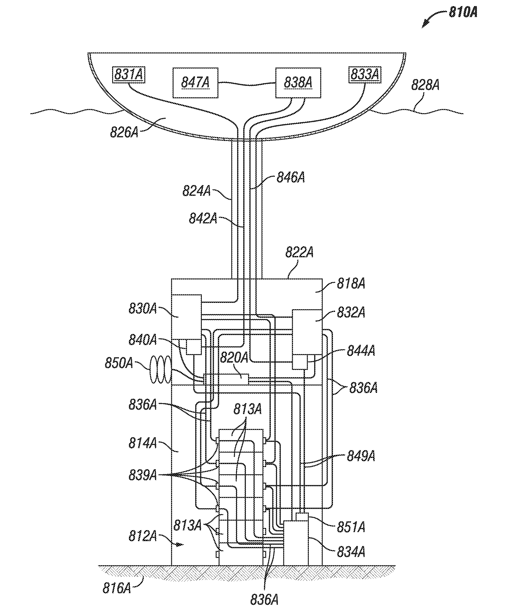
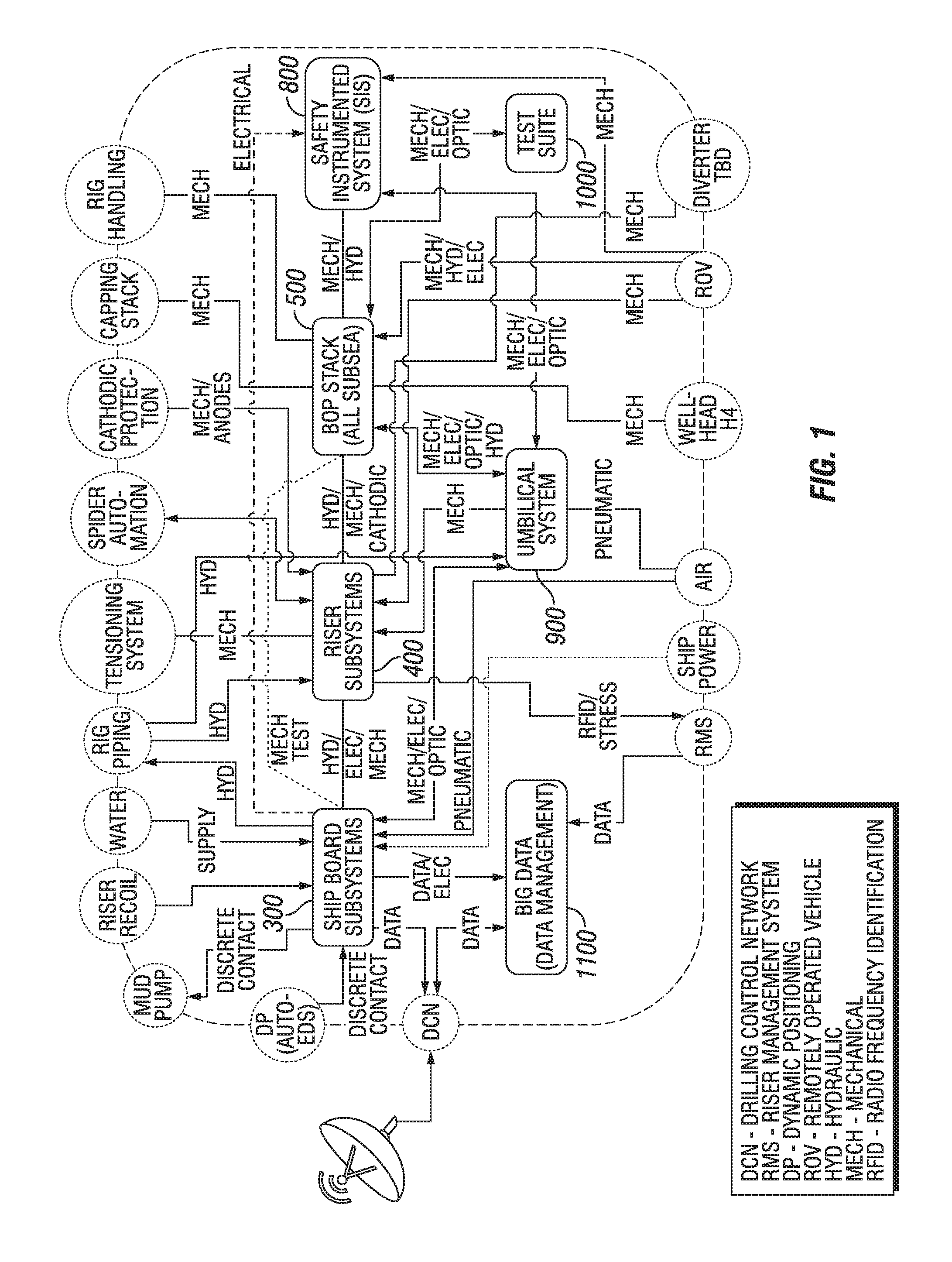
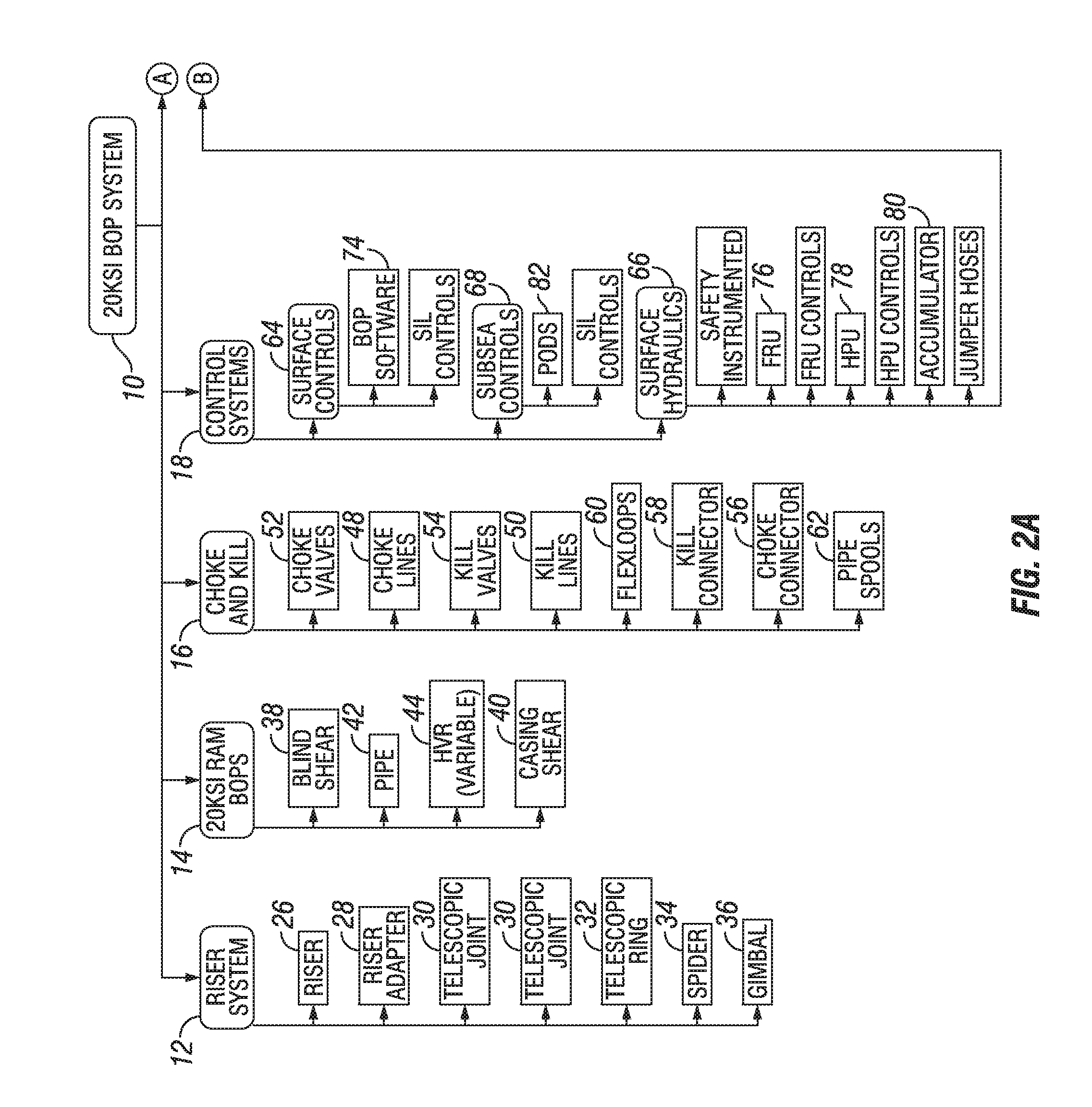
[0008]One aspect of the present technology provides a blowout preventer (BOP) system for use in a high pressure subsea environment. The BOP system includes a BOP stack including a lower marine riser package and a lower stack portion, the lower stack portion having a plurality of BOP rams attached to a subsea wellhead, and a riser subsystem extending from a drilling vessel to the BOP stack and providing fluid communication therebetween. In addition, the BOP system includes a ship board subsystem electronically, mechanically, and hydraulically connected to the BOP stack and the riser subsystem to control the functions of the BOP stack and the riser subsystem, as well as a safety instrumented system having a surface logic solver and at least one subsea logic solver, the safety instrumented system in communication with at least a portion of the BOP rams to act as a redundant control system in case of failure of the ship board subsystem.
[0009]An alternate aspect of the present technology provides a BOP system for use in a high pressure subsea environment that includes a BOP stack connected to a drilling vessel, the BOP stack including a lower marine riser package and a lower stack portion, the lower stack portion having a plurality of BOP rams attached to a subsea wellhead. In addition, the BOP system includes an auxiliary stack test system for connection to the BOP stack to test the BOP stack prior to deployment in order to ensure compliance of the BOP stack with predetermined standards, the auxiliary stack test system having testing hardware and software designed to mimic control system software and hardware to be used during drilling operations in order to effectively test the BOP stack, the auxiliary stack test system comprising a safety integrity level rated system cabinet configured to test a safety instrumented system of the BOP system.
[0010]An alternate aspect of the present technology provides a blowout preventer (BOP) system for use in a high pressure subsea environment that includes a BOP stack including a lower marine riser package and a lower stack portion, the lower sta

Problems solved by technology

With higher pressures, there are greater potential safety and environmental consequences if a well leaks.
For decades, limitations of known drilling technology have prevented the oil and gas industry from dri

Method used


Image

  • High Pressure Blowout Preventer System
  • High Pressure Blowout Preventer System
  • High Pressure Blowout Preventer System

Examples


Embodiment Construction

[0029]The foregoing aspects, features, and advantages of the present technology can be further appreciated when considered with reference to the following description of preferred embodiments and accompanying drawings, wherein like reference numerals represent like elements. The following is directed to various exemplary embodiments of the disclosure. The embodiments disclosed should not be interpreted, or otherwise used, as limiting the scope of the disclosure, including the claims. In addition, those having ordinary skill in the art can appreciate that the following description has broad application, and the discussion of any embodiment is meant only to be exemplary of that embodiment, and not intended to suggest that the scope of the disclosure, including the claims, is limited to that embodiment.

[0030]The below description provides an overview of the systems of the present technology. In it, the subsystems included in the technology identified, and a high level description of ea...


PUM


Abstract

A BOP system for use in a high pressure subsea environment, including a BOP stack including a lower marine riser package and a lower stack portion, the lower stack portion having a plurality of BOP rams attached to a subsea wellhead. The system also includes a riser subsystem extending from a drilling vessel to the BOP stack and providing fluid communication therebetween, a ship board subsystem electronically, mechanically, and hydraulically connected to the BOP stack and the riser subsystem to control the functions of the BOP stack and the riser subsystem, and a safety instrumented system having a surface logic solver and at least one subsea logic solver, the safety instrumented system in communication with at least a portion of the BOP rams to act as a redundant control system in case of failure of the ship board subsystem.

Description

CROSS-REFERENCE TO RELATED APPLICATIONS[0001]This application claims priority to U.S. Provisional Patent Appln. No. 62 / 065,431, which was filed on Oct. 17, 2014, and U.S. Provisional Patent Appln. No. 62 / 067,829, which was filed on Oct. 23, 2014, and is a continuation-in-part of U.S. patent application Ser. No. 14 / 870,249, which was filed on Sep. 30, 2015, the full disclosures of which are hereby incorporated herein by reference in their entirety.[0002]This application also claims priority to U.S. Provisional Patent Appln. Nos. 62 / 078,236, filed Nov. 11, 2014, 62 / 091,160, filed Dec. 12, 2014, 62 / 092,973, filed Dec. 17, 2014, 62 / 093,051, filed Dec. 17, 2014, 62 / 093,083, filed Dec. 17, 2014, 62 / 093,200, filed Dec. 17, 2014, 62 / 093,029, filed Dec. 17, 2014, 62 / 097,845, filed Dec. 30, 2014, 62 / 103,817, filed Jan. 15, 2015, 62 / 105,445, filed Jan. 20, 2015, 62 / 105,379, filed Jan. 20, 2015, 62 / 147,210, filed Apr. 14, 2015, 62 / 155,671, filed May 1, 2015, 62 / 158,364, filed May 7, 2015, and 6...

Claims


Application Information

Patent Timeline
IPC IPC(8): G05B19/406E21B33/06E21B33/035
CPCG05B19/406G05B2219/37399E21B33/061E21B33/0355E21B33/064E21B34/16
Inventor HOLMES, JOHN STEVENMILLIMAN, DOUGLASHUERTA, LUIS E.LARSON, ERIC DALEGILLETTE, GREGORY RONALDJUDGE, ROBERT ARNOLDSHAH, VIRAL
Owner HYDRIL USA DISTRIBUTION LLC
Why Eureka
Try Eureka