Apparatus for wireless power transfer, apparatus for wireless power reception and coil structure

a technology for wireless power transmission and apparatus, applied in multiple-port networks, transformers, inductances, etc., can solve the problems of complex receiving circuits and skin effects, and achieve the effects of reducing dead zones, effective interworking, and increasing the strength of magnetic fields

Active Publication Date: 2016-04-21
KOREA ELECTROTECH RES INST
View PDF4 Cites 34 Cited by
  • Summary
  • Abstract
  • Description
  • Claims
  • Application Information

AI Technical Summary

Benefits of technology

[0039]According to an embodiment of the present invention, the present invention allows wireless charging even though the locations of a transmitting coil and a receiving coil are not aligned, and may provide a wireless power transceiver system capable of simultaneously transmitting power to multiple receiving devices.
[0040]Also, according to an embodiment of the present invention, it is possible to provide a wireless power transmitting device in which a dead zone is minimized based on the improved structures of a horizontal coil unit and a vertical coil unit, and a wireless power receiving device having a structure capable of effectively interworking with the wireless power transmitting device.
[0041]Also, according to an embodiment of the present invention, a wire-winding method for increasing the strength of a magnetic field and decreasing the loss resistance of a coil may be provided to raise the transmission efficiency.

Problems solved by technology

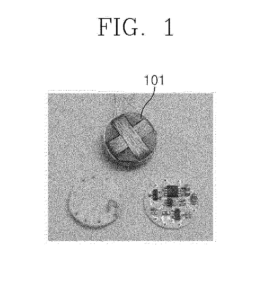
The three-axis receiving coil 101 illustrated in FIG. 1 has a disadvantage in that a receiving circuit is complicated because rectifier circuits are included for each receiving coil when a wireless power transmission system is implemented.
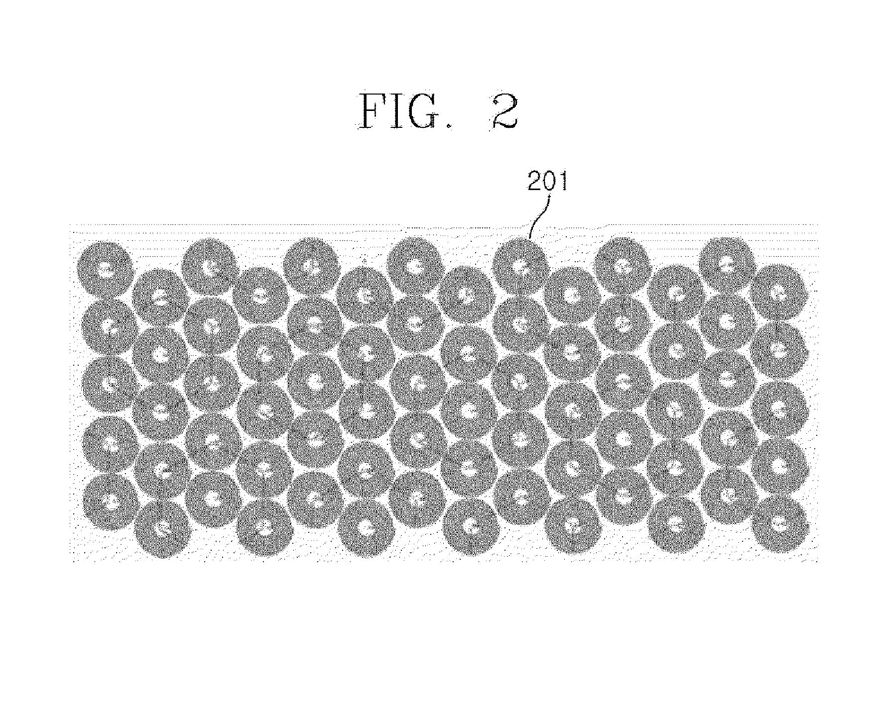
However, during wireless power transmission in a frequency range higher than several MHz, a skin effect, in which current is concentrated in the outer layer of a conducting wire because of eddy currents, is caused.

Method used


Image

  • Apparatus for wireless power transfer, apparatus for wireless power reception and coil structure
  • Apparatus for wireless power transfer, apparatus for wireless power reception and coil structure
  • Apparatus for wireless power transfer, apparatus for wireless power reception and coil structure

Examples


Embodiment Construction

[0090]Hereinafter, various embodiments for a coil structure according to an embodiment of the present invention will be described in detail.

[0091]FIG. 4 is a perspective view illustrating an example of a coil structure according to an embodiment of the present invention, and FIG. 5 is an exemplary view for describing the coil structure illustrated in FIG. 4. Specifically, the views illustrate an example of the structure of a 3-dimensional wireless power transmitting coil for minimizing a dead zone in wireless power transmission.

[0092]A transmitting coil 400 according to an embodiment of the present invention, illustrated in FIGS. 4 and 5, may include a multi-loop coil unit 401 formed as a circular spiral coil on a 2-dimensional plane, for example, on the floor, and a helical coil unit 402 having a conical-like form, in which a coil is wound to the vertical direction from the plane on which the multi-loop coil unit is formed but the radius of the coil loop steadily increases.

[0093]In...


PUM

PropertyMeasurementUnit
angleaaaaaaaaaa
angleaaaaaaaaaa
diameteraaaaaaaaaa

Abstract

The present invention relates to a transmitting device for wireless power transmission, which includes: a bowl-shaped transmitting device body; and a transmitting coil unit for wirelessly transmitting power to a receiving device based on power supplied from a power source. The transmitting coil unit may include a multi-loop coil unit wound in the bottom surface of the transmitting device body, and a helical coil unit wound around the side wall of the transmitting device body, the helical coil unit being wound to increase the radius of a coil loop in a direction to the upper part of the transmitting device body, and being extended from the end of the multi-loop coil unit.

Description

CROSS-REFERENCE TO RELATED APPLICATIONS[0001]The present application is a Continuation-In-Part of International Application No. PCT / KR2014 / 011398 filed on Nov. 26, 2014, which claims priority to Korean Patent Application No. 10-2014-0052704 filed on Apr. 30, 2014 and Korean Patent Application No. 10-2014-0118921 filed on Sep. 5, 2014, the disclosures of which are hereby incorporated in their entirety by reference.TECHNICAL FIELD[0002]The present invention generally relates to a wireless power transmitting device, a wireless power receiving device, and a coil structure. More specifically, the present invention relates to wireless charging technology capable of wirelessly transmitting power from a wireless power transmitting device to one or more wireless power receiving devices effectively, based on non-radiative near-field magnetic coupling.BACKGROUND ART[0003]Generally, wireless power transmission technology based on near-field magnetic coupling is technology for wirelessly transmi...

Claims


Application Information

Patent Timeline
Patent Type & Authority Applications(United States)
IPC IPC(8): H01F38/14H01F27/28H03H7/38H02J5/00
CPCH01F38/14H03H7/38H01F27/2823H02J5/005H01F27/006H02J50/10
Inventor PARK, YOUNG JINKIM, JIN WOOKKIM, KWAN HOKIM, DO HYUNYANG, JONG RYUL
Owner KOREA ELECTROTECH RES INST
Why Eureka
Try Eureka