

Power module
a power module and power technology, applied in the field of power modules, can solve the problems of high heat generation, low maintenance cost of industrial system-level products, and long life time and low maintenance cost of industrial system-level products, and achieve the effect of improving the reliability of bonding materials and cost-effectiveness
- Summary
- Abstract
- Description
- Claims
- Application Information
AI Technical Summary
Benefits of technology
Problems solved by technology
Method used
Image

Examples
Embodiment Construction
[0028]References will be introduced in detail to describe the present embodiments of the disclosure, which are illustrated in the accompanying drawings. Wherever possible, the same reference numbers are used in the drawings and the description to refer to the same or like parts.
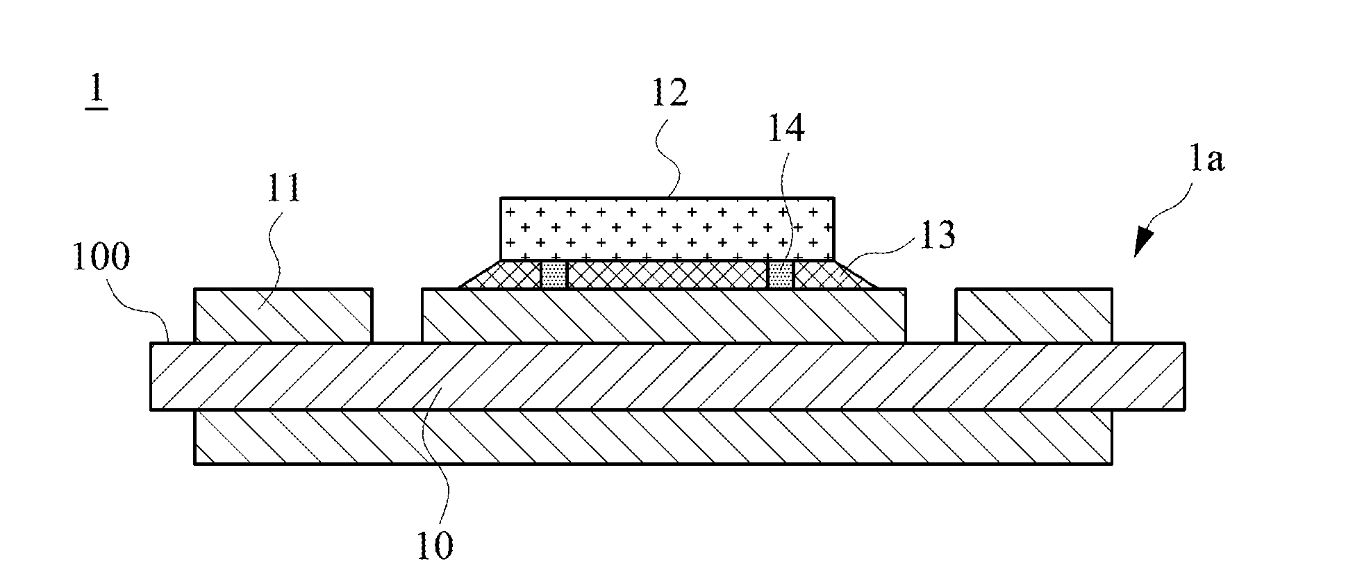
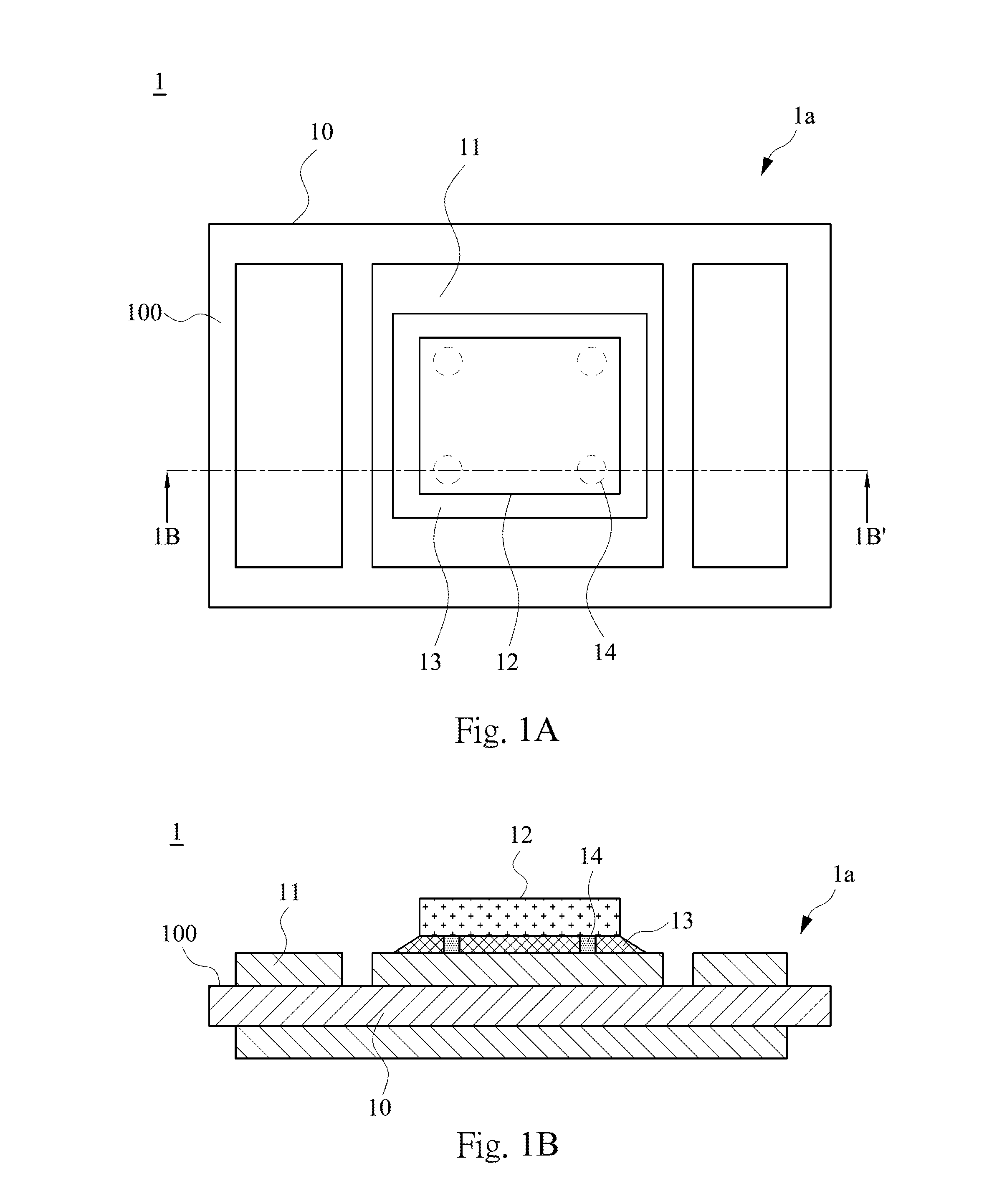
[0029]FIG. 1A demonstrates a top view of a power module 1 according to an embodiment of the disclosure. FIG. 1B demonstrates a cross-sectional view of the power module 1 in FIG. 1A along line 1B-1B′. In the embodiment, the power module 1 includes a substrate 1a, a power chip 12, a bonding material 13, and spacers 14. The substrate 1a includes an insulating layer 10 and a circuit-patterned layer 11. The insulating layer 10 has a surface 100. The circuit-patterned layer 11 is located on the surface 100. The power chip 12 is bonded to the circuit-patterned layer 11 by the bonding material 13. The spacers 14 are employed as supports between the circuit-patterned layer 11 and the power chip 12. The smallest thickn...
PUM
 Abstract
Description
Claims
Application Information