
Vehicle link component, and manufacturing method therefor

a technology for vehicle link components and manufacturing methods, applied in the direction of transportation and packaging, other domestic articles, fastening means, etc., can solve the problems of damage to the link body, inability to form a standing surface by burring processing, and inability to employ the method for a vehicle link component formed from cfrp

Inactive Publication Date: 2016-04-28
TORAY IND INC +1
View PDF32 Cites 10 Cited by
  • Summary
  • Abstract
  • Description
  • Claims
  • Application Information

AI Technical Summary

Benefits of technology

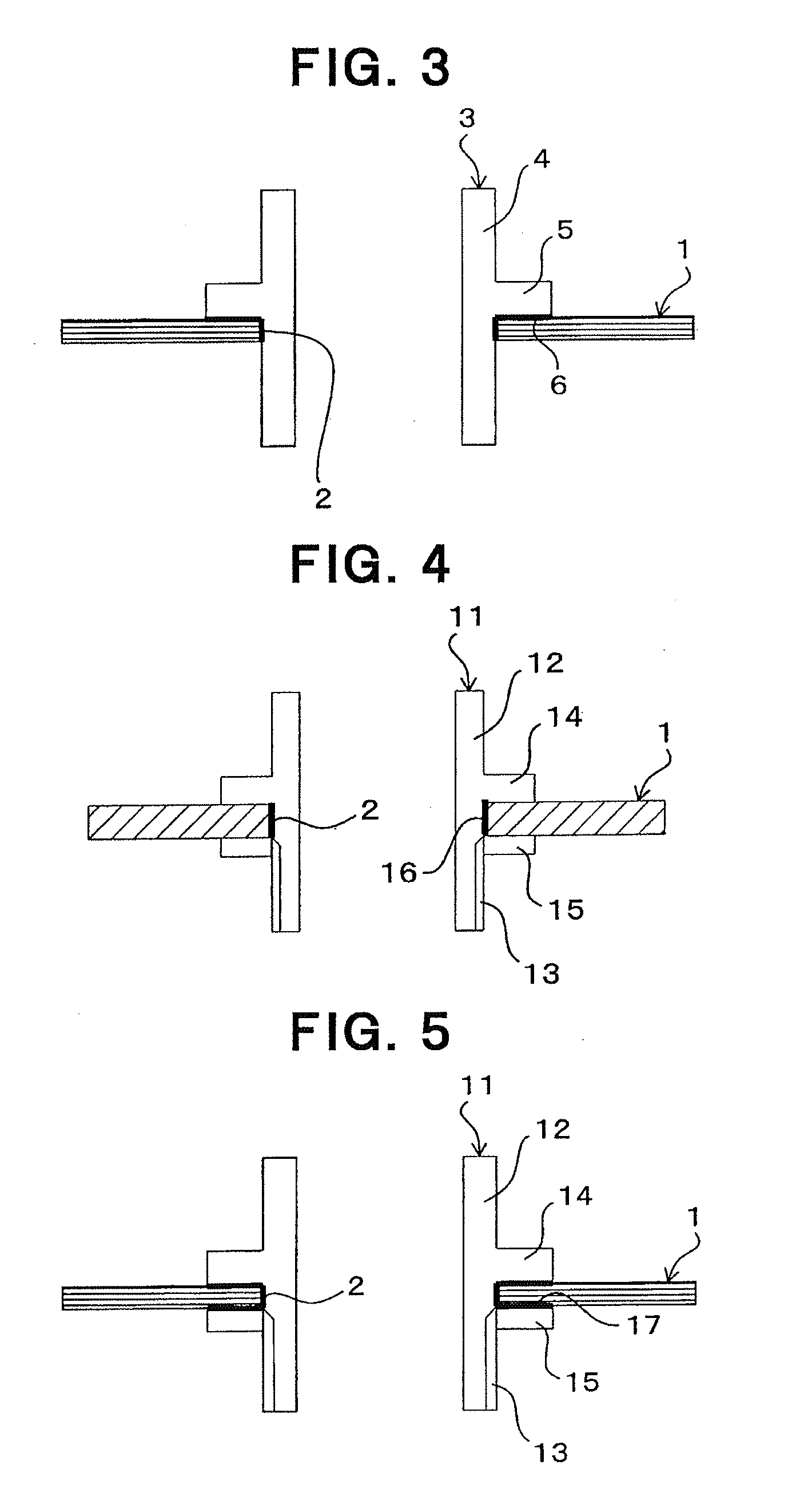
The present invention provides a vehicle link component that is made from a lightweight material, such as CFRP, which can reduce the weight of the component without compromising its strength. The component includes a collar member that is separate from the link body, which makes it easier to mount the rotation fulcrum member without causing damage to the link body. The collar member is easily fixed to the link body by inserting its cylindrical section into a hole section and bringing its engagement section into contact with the link body's surface. The collar member can be fixed with two engagement sections, which further increases the connection strength between the link body and the rotation fulcrum member. The collar member can be fixed using nuts and bolts or a retaining ring, and the design of the collar member allows for easy assembly and compatibility with various parts in the assembly. Overall, the invention provides a lightweight and strong vehicle link component that can be easily assembled without causing damage.

Problems solved by technology

Although CFRP has been used for reducing the weight of a vehicle compartment and for other purposes in recent years, because CFRP does not deform plastically, it is almost impossible to form a standing-up surface by burring processing.
Even if a standing-up surface is formed in a link body at a molding stage by using a mold or the like, there occurs a possibility that a damage is caused in the link body if a bush or the like is press-fitted directly into the attachment section.
However, because welding cannot be applied to a link body formed from CFRP, this method cannot be employed for a vehicle link component formed from CFRP.

Method used


Image

  • Vehicle link component, and manufacturing method therefor
  • Vehicle link component, and manufacturing method therefor
  • Vehicle link component, and manufacturing method therefor

Examples


Embodiment Construction

[0027]Hereinafter, embodiments of the present invention will be explained referring to figures.

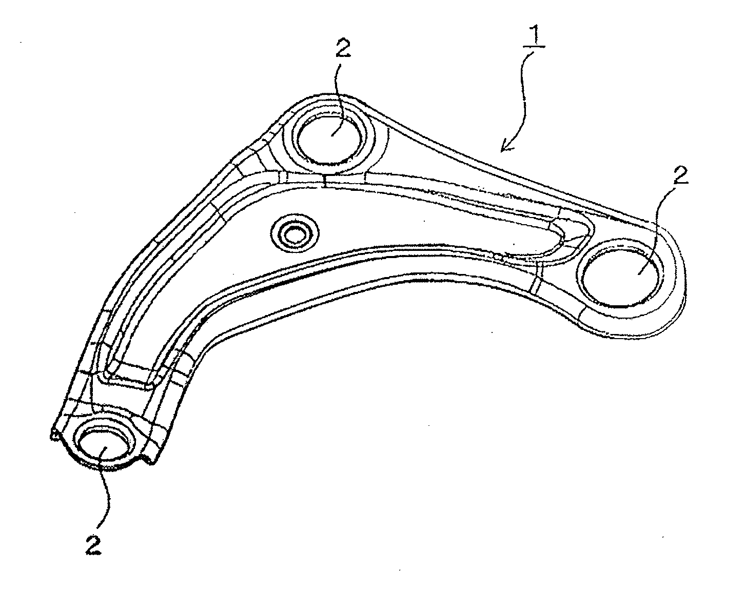
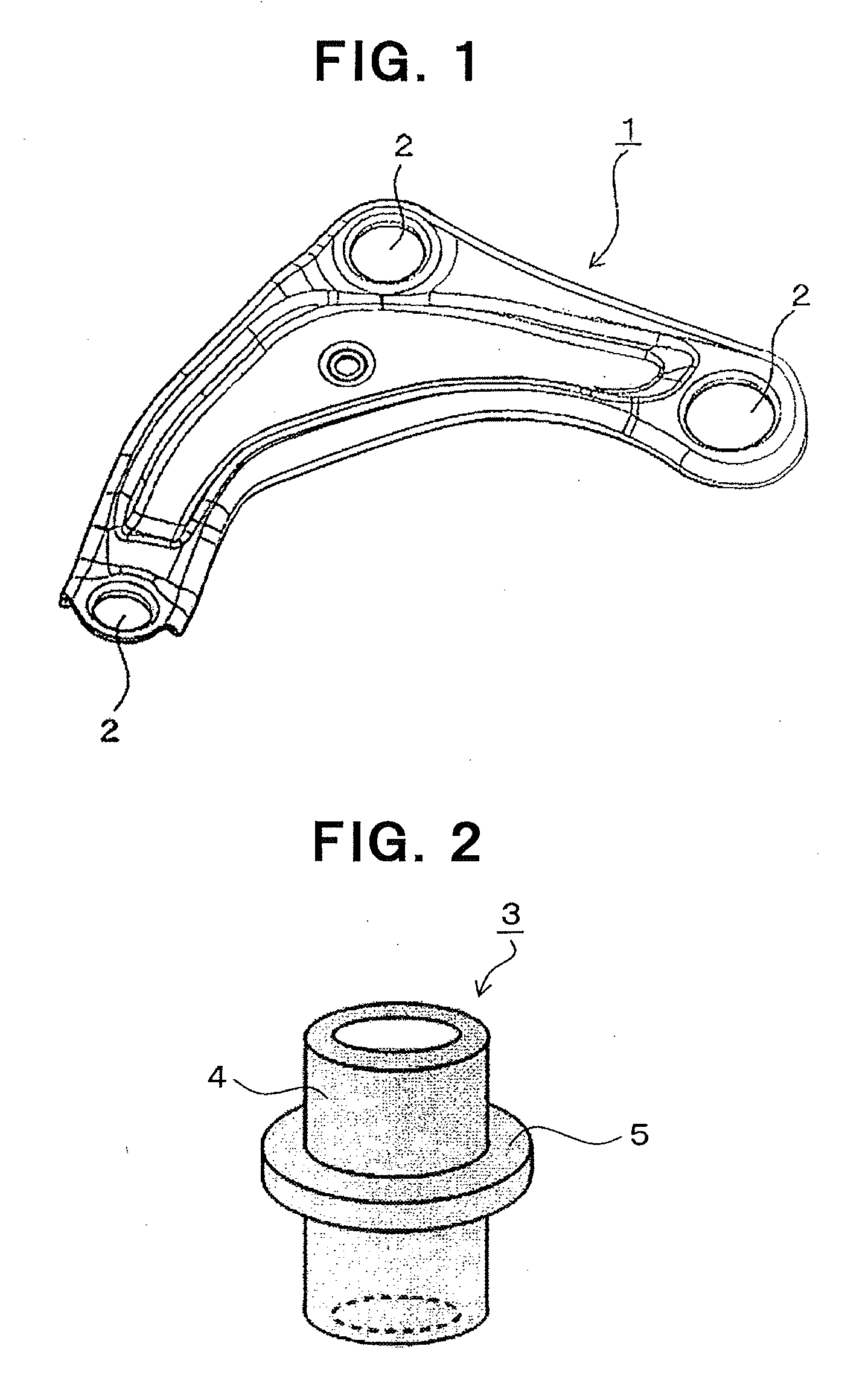
[0028]FIG. 1 shows a suspension arm 1 as a link body in a vehicle link component according to an embodiment of the present invention, and this suspension arm 1 is formed as a molded article of a carbon-fiber reinforced plastic (CFRP). The molding method of CFRP is not particularly restricted, and RTM (Resin Transfer Molding) method, so-called vacuum-assisted RTM method accompanying with pressure reduction in a mold, etc. can be applied. Further, the kind of carbon fibers used as reinforcing fibers also is not particularly restricted, and the content thereof also is not particularly restricted. Furthermore, the kind of a matrix resin also is not particularly restricted, and both thermoplastic resin and thermosetting resin can be used.

[0029]To the above-described suspension arm 1 as a link body, for its own rotation fulcrum, or, for a rotation fulcrum for connection between it and another me...


PUM

PropertyMeasurementUnit
Weightaaaaaaaaaa
Diameteraaaaaaaaaa

Abstract

The present invention comprises: a vehicle link component which is characterized in that a collar member is provided to a rotation fulcrum member-mounting hole section of a link body formed from carbon-fiber reinforced plastic (CFRP), said collar member having a cylindrical section that extends inside the hole section in the direction of penetration of the hole section, and having an engagement section that extends in the direction along the surface of the link body from the cylindrical section; and a manufacturing method therefor. By employing the CFRP link body, a significant reduction in the weight of the vehicle link component can be achieved, and assembly can easily be performed as desired without causing damage by press-fitting a bush, or the like, even in the CFRP link body.

Description

TECHNICAL FIELD OF THE INVENTION[0001]The present invention relates to a vehicle link component and a manufacturing method therefor, and specifically, to a vehicle link component in which a link body is formed from a carbon-fiber reinforced plastic (CFRP), and a manufacturing method therefor.BACKGROUND ART OF THE INVENTION[0002]A vehicle link component, for example, a suspension arm or the like, is frequently formed from a metal such as a steel or an aluminum alloy. In such a metal link component formed from a steel, an aluminum alloy, etc., in an attachment section provided to a link body for mounting a rotation fulcrum member such as a ball joint, a bush, etc., a standing-up surface is formed by carrying out burring processing onto the link body, and the rotation fulcrum member is mounted to a hole section surrounded by the standing-up surface portion by being press-fitted or the like to the hole section (for example, Patent documents 1 and 2).[0003]Although CFRP has been used for...

Claims


Application Information

Patent Timeline
IPC IPC(8): B60G7/00B29C65/48B29C65/00B21D53/88
CPCB60G7/001B21D53/88B29C65/48B29C66/7212B29C66/742B29L2031/737B60G2206/122B60G2206/7101B60G2206/821B60G2206/8207B29L2031/3002B60G2200/1424B29C66/1222B29C66/1224B29C66/12441B29C66/131B29C66/53245B29C66/7392B29C66/7394B60G7/008B60G7/02B60G2204/14B60G2206/91F16B11/006F16B9/01B29K2307/04
Inventor IWASAWA, SHIGEOKURODA, YOSHITOKAWAGUCHI, SHUICHIROMORIWAKI, YOSHIHIROTABATA, SHOTA
Owner TORAY IND INC
Learn More