Combustion plate

a technology of combustion plate and combustion chamber, which is applied in the direction of combustion type, burner material specification, burner, etc., can solve the problems of premixed gas that recirculates back, flashbacks are likely to occur, and interfere with each other

Active Publication Date: 2016-04-28
RINNAI CORP
View PDF17 Cites 17 Cited by
  • Summary
  • Abstract
  • Description
  • Claims
  • Application Information

AI Technical Summary

Benefits of technology

[0009]In view of the above points, it is an advantage of the invention to provide a combustion plate that is capable of improving the resistivity against flashback.
[0010]In order to solve the above-mentioned problems, the invention is a combustion plate for use in a totally aerated combustion burner in which a plate main body made of ceramic has formed therein a multiplicity of flame holes for ejecting a premixed gas. The plate main body is provided, in a lattice shape, with non-flame-hole sections free of flame holes. Each of those sections of the plate main body which are enclosed by the non-flame-hole sections constitutes a collective flame-hole section having formed therein in a crowded manner a plurality of flame holes. Flame holes formed in those peripheral portions of the collective flame-hole sections which are adjacent to the non-flame-hole sections are smaller in diameter than the diameter of the flame holes formed in those portions of the collective flame-hole sections which are inner than the peripheral portions.
[0011]According to this invention, by making smaller in diameter the flame holes formed in those peripheral portions of the collective flame-hole sections (the flame holes in question are called “peripheral flame holes”), the amount of premixed gas to be ejected from the peripheral flame holes is reduced, and the amount of heating the non-flame-hole portions due to the combustion of the premixed gas can be reduced. As a result, as compared with a case in which the diameter of the peripheral flame holes is not made smaller, the temperature of the non-flame-hole sections at the time of low-load combustion can be lowered, thereby improving the resistivity against flashback.
[0012]Further, in this invention, in a manner similar to that in the known example as described in the above-mentioned Patent Document 2, preferably, the flame holes are formed in each of those side portions of the non-flame-hole sections which are adjacent to the respective collective flame-hole sections, the flame holes being formed at a predetermined spacing from one another in a longitudinal direction of the non-flame-hole sections. And the predetermined spacing is set larger than the spacing from one another of the flame holes formed in the collective flame-hole sections as seen in a direction parallel to the longitudinal direction of the non-flame-hole sections. Then, flame lifting at the peripheral portions of the collective flame-hole sections can be prevented. In this case, since the flame holes formed in each of the side portions of the non-flame-hole sections (the flame holes are called “outside flame holes”) are small in number, the diameter of the outside flame holes need not be made smaller. Instead, the peripheral flame holes may be made smaller in diameter. The temperature of the non-flame-hole portions can thus be lowered at the time of low-load combustion. In this invention, however, the outside flame holes shall preferably be made also smaller in diameter than the diameter of the flame holes formed in those portions of the collective flame-hole sections which are inner than the peripheral portions. According to this arrangement, by reducing the amount of the premixed gas to be ejected from the outside flame holes, the amount of heating the non-flame-hole sections by combustion of the premixed gas can be reduced. By still further lowering the temperature of the non-flame-hole sections at the time of low-load combustion, the resistivity against flashback can further be improved.

Problems solved by technology

Then, the premixed gas that recirculates back from the flame holes around the periphery of the collective flame-hole sections that are positioned on both sides of the non-flame-hole sections interfere with each other.
However, the arrangement referred to above has a disadvantage in that flashback is likely to occur at the time of low-load combustion.
In other words, at the non-flame-hole sections, there cannot be obtained an effect of cooling the plate main body by the premixed gas that flows through the flame holes.
Hence the resistivity (performance) against flashback cannot sufficiently be improved.

Method used


Image

  • Combustion plate
  • Combustion plate
  • Combustion plate

Examples


Embodiment Construction

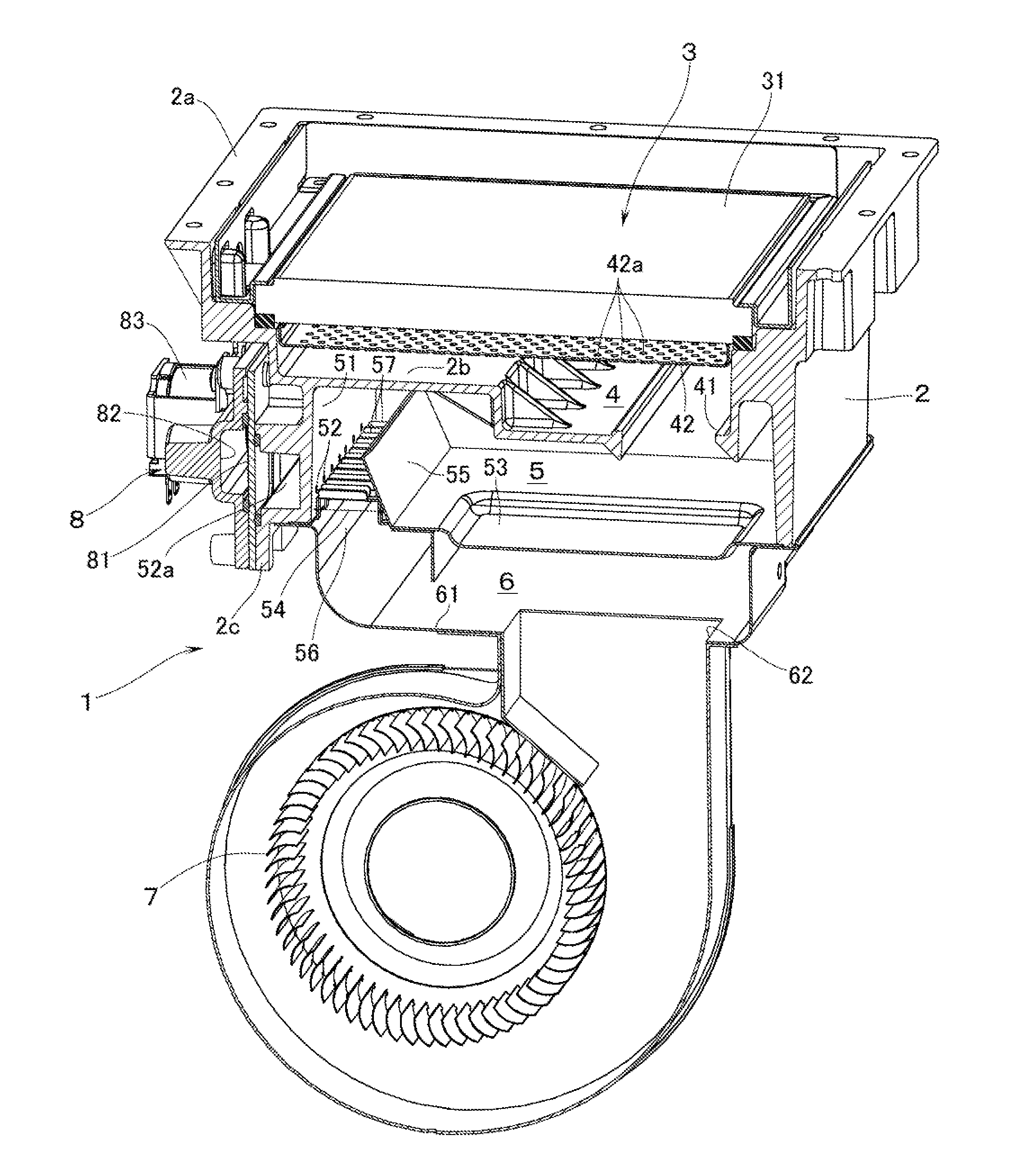
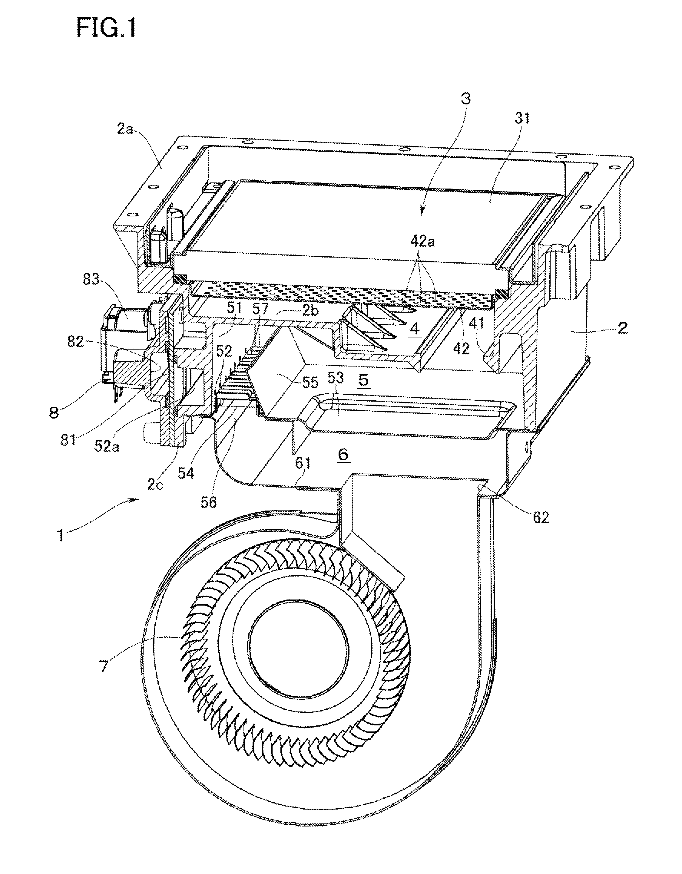
[0017]With reference to FIG. 1, reference numeral 1 denotes a totally aerated combustion burner (or a fully primary aerated burner). The burner 1 has a burner main body 2 which is formed into a box shape so as to open upward, and a combustion plate 3 which is mounted on an upper part of the burner main body 2. Description will be made hereinafter on condition that the width direction of the burner 1 is defined as a lateral side direction and that the depth direction of the burner 1 is defined as a longitudinal (back-and-forth) direction.

[0018]Around an outer periphery of the upper surface of the burner main body 2, there is disposed a flange portion 2a to which is connected a lower end of a combustion housing (not illustrated) in which are housed a heat exchanger for supplying hot water or for heating a residential space. Further, the burner main body 2 is provided therein with: a distribution chamber 4 which faces the lower surface of the combustion plate 3; and, on the lower side ...


PUM


Abstract

A combustion plate is for use in a totally aerated combustion burner in which a plate main body made of ceramic has formed therein a multiplicity of flame holes for ejecting a premixed gas. The plate main body is provided, in a lattice shape, with non-flame-hole sections free of flame holes. Each of those sections of the plate main body which are enclosed by the non-flame-hole sections constitutes a collective flame-hole section having formed therein in a crowded manner a plurality of flame holes. Flame holes formed in those peripheral portions of the collective flame-hole sections which are adjacent to the non-flame-hole sections are smaller in diameter than the diameter of the flame holes formed in those portions of the collective flame-hole sections which are inner than the peripheral portions.

Description

BACKGROUND OF THE INVENTION[0001]1. Field of the Invention[0002]The present invention relates to a combustion plate for use in a totally aerated combustion burner (or a fully primary aerated burner) in which a plate main body made of ceramic has formed therein a multiplicity of flame holes (burner holes) for ejecting a premixed gas. The combustion plate is disposed in a heat source equipment mainly for supplying hot water or for heating a residential space.[0003]2. Description of the Related Art[0004]As this kind of combustion plate, there is known one in which non-flame-hole sections (i.e., sections free of flame holes, or sections having no flame holes) are formed on a plate main body in a lattice shape, and in which each of the sections of the plate main body enclosed by the non-flame-hole sections is arranged to be a collective flame-hole section having formed therein in a crowded manner a plurality of flame holes (see, for example, Patent Document 1, i.e., JP-UM-A-1995-12713). ...

Claims


Application Information

Patent Timeline
Patent Type & Authority Applications(United States)
IPC IPC(8): F23D14/14F23D14/02
CPCF23D14/14F23D14/02F23D2212/10F23D2900/00003F23D2203/1023F23D2203/005F23D14/74F23D14/82F23D14/145
Inventor TAKEUCHI, MASARU
Owner RINNAI CORP
Why Eureka
Try Eureka