Optical fiber fusion splicer and optical fiber fusion splicing apparatus provided with same

a technology of optical fiber fusion splicing and optical fiber fusion, which is applied in the direction of optical elements, manufacturing tools, instruments, etc., can solve the problems of increasing the height the difficulty of performing maintenance work from above the apparatus, and the size of the entire mechanism, so as to reduce suppress the occurrence of distortion in the fixed base, and the effect of reducing the size of the fixed bas

Active Publication Date: 2016-04-28
THE FUJIKURA CABLE WORKS LTD
View PDF1 Cites 5 Cited by
  • Summary
  • Abstract
  • Description
  • Claims
  • Application Information

AI Technical Summary

Benefits of technology

[0038]According to the above aspects of the present invention, the distance L1 between one end portions of the pair of elastic members in the fixed base is configured to be short, whereby it becomes possible to reduce the size of the fixed base, and therefore, it is possible to suppress occurrence of distortion in the fixed base. In this manner, breakage of the optical fiber fusion splicer or a decrease in alignment accuracy of the optical fibers can be prevented and it becomes possible to attain a reduction in the size and the weight of the entire optical fiber fusion splicing apparatus.
[0039]In addition, the pair of elastic members is fixed so as to extend upward from the fixed base while being respectively inclined in the forward and backward directions and is disposed at positions shifted in the right-left direction and a connection portion of the V-grooved stand to the elastic member is disposed at a position away from a fusion splicing portion in which the tips of the pair of optical fibers are brought into contact with each other, and therefore, there is no interference with the right and left fiber clamps, the movable stages driving forward the fiber clamps, or the like. In this manner, it is not necessary to increase the height of the V-grooved stand, and thus it becomes possible to reduce the height of the optical fiber fusion splicer. Therefore, a reduction in the size and the weight of the entire optical fiber fusion splicing apparatus becomes possible.
[0040]Furthermore, the pair of elastic members is fixed so as to extend upward while being inclined in the forward and backward directions and is disposed at positions shifted in the right-left direction, and therefore, drive mechanisms such as the micrometers for elastically deforming the elastic members can be disposed on the upper side, backward and forward away from a fusion splicing portion. Therefore, it becomes easy to perform maintenance work of the drive mechanisms from above the optical fiber fusion splicing apparatus, and thus maintainability is improved.

Problems solved by technology

H08-62446, similar to the above, the distance between the connection portions of the elastic members to the fixed base is large, and therefore, in a case where the rigidity of the fixed base is low, the same problem occurs.
For this reason, in the fusion splicer of the related art, there is a problem in that the height of the entire mechanism is increased.
H08-62446, the elastic member on one side is disposed just below the V-grooved stand, and therefore, similar to the above, there is a problem in that the height of the entire mechanism is increased.
For this reason, a drive mechanism such as the micrometer 105A for elastically deforming the pair of elastic members 103A and 103B is disposed on the lower side of the apparatus, and therefore, there is a problem in that it is difficult to perform maintenance work from above the apparatus.

Method used


Image

  • Optical fiber fusion splicer and optical fiber fusion splicing apparatus provided with same
  • Optical fiber fusion splicer and optical fiber fusion splicing apparatus provided with same
  • Optical fiber fusion splicer and optical fiber fusion splicing apparatus provided with same

Examples


first embodiment

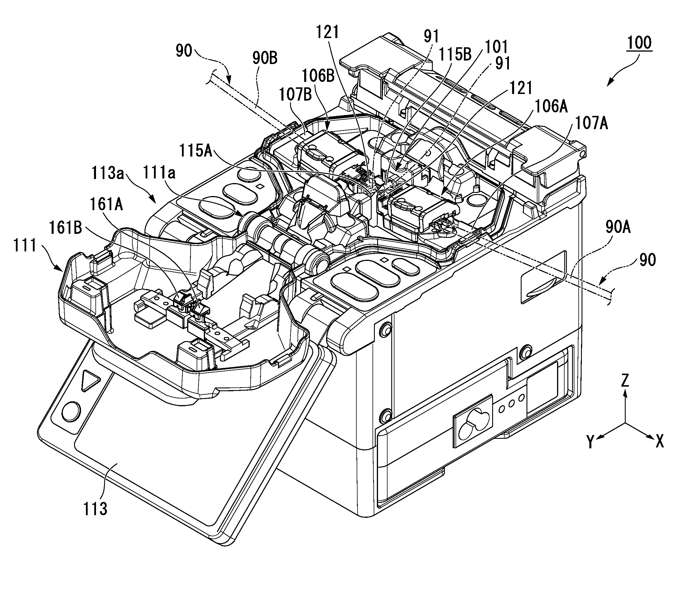
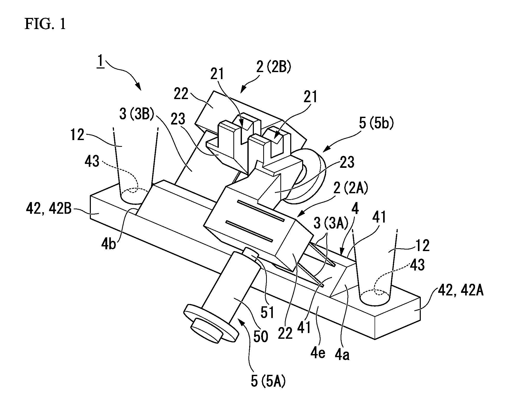
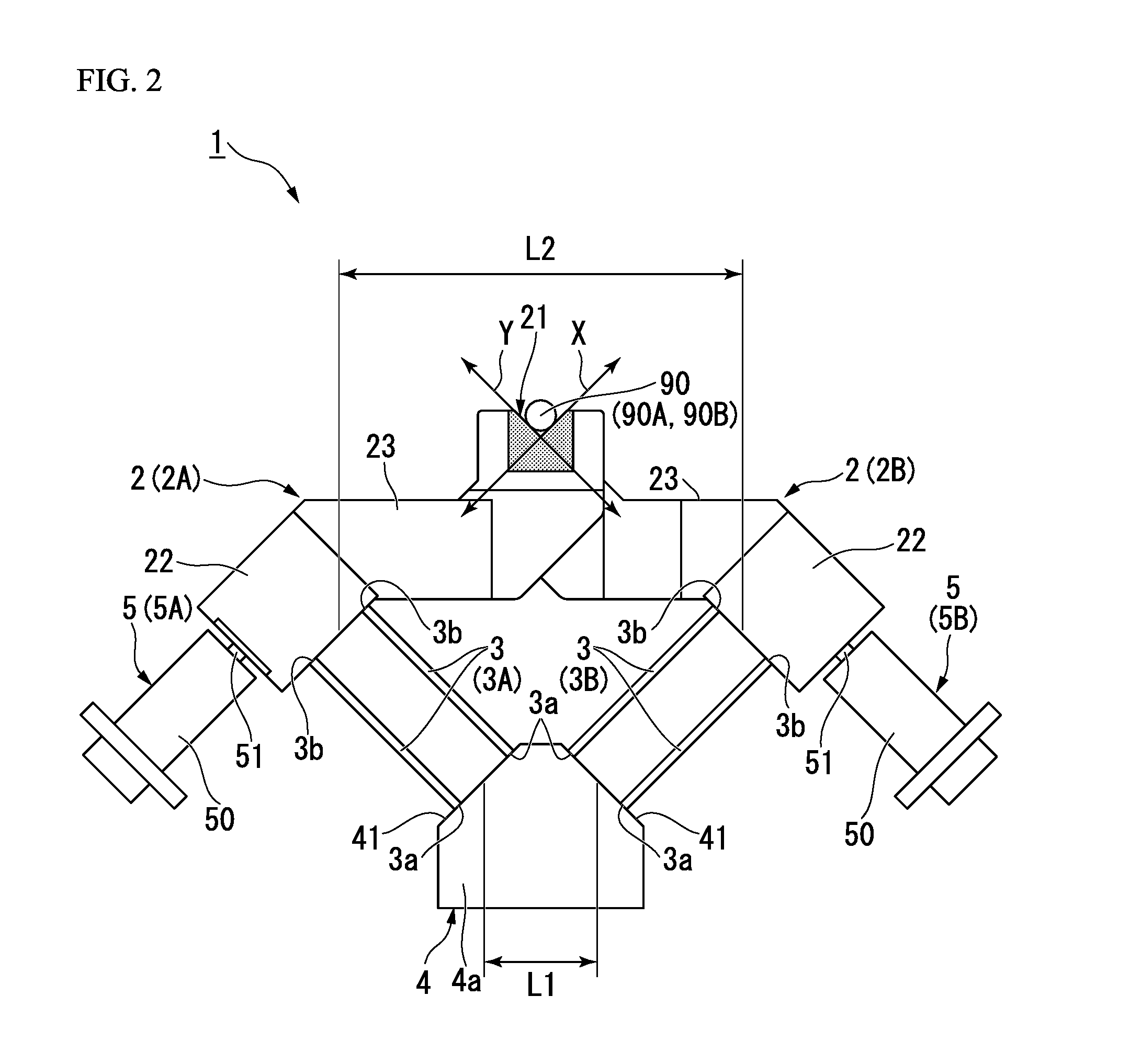
[0059]Hereinafter, an optical fiber fusion splicer of a first embodiment of the present invention will be described in detail using FIGS. 1 to 5. In addition, configurations which are not shown in FIGS. 1 to 5 are sometimes described while appropriately citing FIG. 8 which is the overall perspective view of an optical fiber fusion splicing apparatus of the related art, as necessary. Further, the drawings which are referred to in the present embodiment are sometimes appropriately used in other embodiments as well, and for example, even in a case where disposition positions or the like of configurations are different from each other in the embodiments, configurations having the same function are sometimes described with the same reference numerals applied thereto.

[0060]Further, each drawing which is referred to in the following description is for schematically describing the fusion splicer with which the optical fiber fusion splicing apparatus of the present embodiment is provided, an...

second embodiment

[0107]Hereinafter, an optical fiber fusion splicer 1A of a second embodiment of the present invention will be described mainly referring to FIGS. 6 and 7. In addition, in the present embodiment, a portion is described with reference to the same drawings as those in the first embodiment described above, and a common configuration described previously, for example, the pair of micrometers 5 which aligns the tips 91a of the pair of optical fibers 90A and 90B while elastically deforming the elastic members by pressing the V-grooved stands, or the like is denoted by the same reference numeral and the detailed description thereof is omitted.

[0108]As shown in FIGS. 6 and 7 (FIG. 3 is also referred to), the fusion splicer 1A of the present embodiment is for aligning the tips 91a of the pair of optical fibers 90A and 90B, thereby bringing the tips 91a into contact with each other, and fusion-splicing the core wires of the pair of optical fibers by discharge heating, similar to the fusion spl...


PUM

PropertyMeasurementUnit
angleaaaaaaaaaa
distance L1aaaaaaaaaa
distance L2aaaaaaaaaa

Abstract

An optical fiber fusion splicer includes: a pair of right and left V-grooved stands having V-grooves for butting tips of a pair of optical fibers each other while positioning the tips of a pair of optical fibers; a pair of elastic members respectively supporting the pair of V-grooved stands and formed into the form of an elastically deformable plate; a fixed base on which the pair of elastic members is mounted, whereby the pair of V-grooved stands is fixed thereto through the pair of elastic members, and which is long in a right-left direction; and a pair of micrometers aligning the tips of the pair of optical fibers by finely moving the pair of V-grooved stands with respect to each other while elastically deforming the pair of elastic members by pressing the pair of V-grooved stands from forward and backward directions.

Description

CROSS REFERENCE TO RELATED APPLICATIONS[0001]Priority is claimed on Japanese Patent Application No. 2014-217246, filed on Oct. 24, 2014, the content of which is incorporated herein by reference.BACKGROUND OF THE INVENTION[0002]1. Field of the Invention[0003]The present invention relates to an optical fiber fusion splicer and an optical fiber fusion splicing apparatus which is provided with the optical fiber fusion splicer.[0004]2. Description of Related Art[0005]When performing a fusion splice of an optical fiber, in general, the fusion splice is performed in the following procedure by using an optical fiber fusion splicing apparatus.[0006](1) An optical fiber core wire is extracted from an optical fiber cable.[0007](2) A resin coating (a tip) covering the extracted optical fiber core wire is removed by an optical fiber coating removal tool.[0008](3) Resin coating debris remaining on the surface of glass (a bare optical fiber) of the optical fiber core wire with the coating of the t...

Claims


Application Information

Patent Timeline
Patent Type & Authority Applications(United States)
IPC IPC(8): G02B6/255
CPCG02B6/2553G02B6/2557G02B6/2551
Inventor SASAKI, KATSUMI
Owner THE FUJIKURA CABLE WORKS LTD
Why Eureka
Try Eureka