
A user interface for a surgical simulation system

a technology of user interface and simulation system, which is applied in the field of user interface devices for surgical simulation systems, can solve the problems of unsatisfactory resolution of such applications, unnecessarily complicating surgery, and large pivoting joints

Inactive Publication Date: 2016-04-28
SURGICAL SCI SWEDEN
View PDF37 Cites 45 Cited by
  • Summary
  • Abstract
  • Description
  • Claims
  • Application Information

AI Technical Summary

Benefits of technology

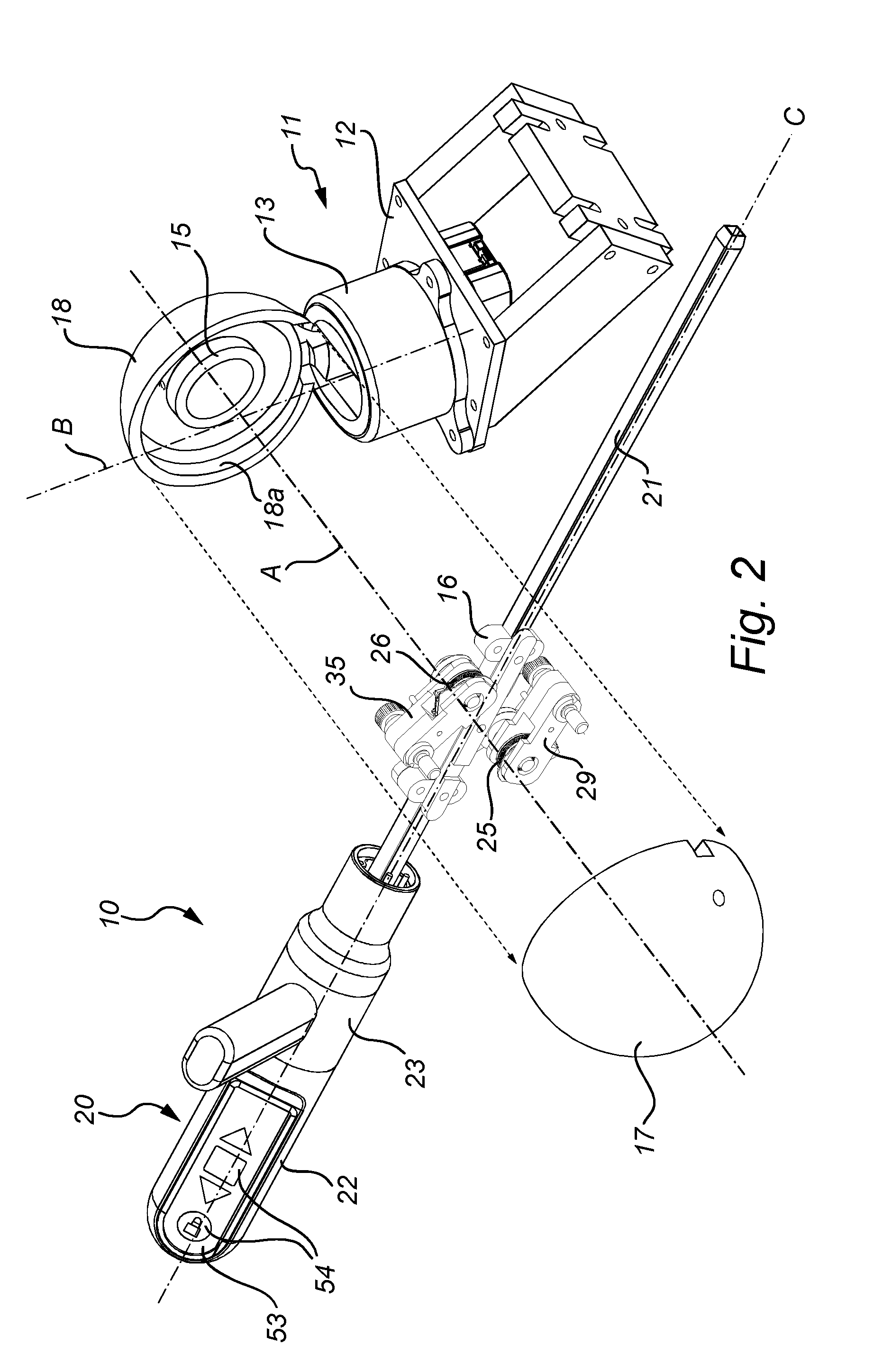
The present invention helps solve the problem of low resolution in rotational detection by using a small rotational sensor and optimizing space usage. By arranging the guiding surface radially outside the roller with respect to the first axis, the available space is used effectively. A rigid shaft may be fixed in relation to the suspension portion with respect to rotation around the longitudinal axis, which eliminates the need for yet another sensor in the suspension portion and makes it easier to detect rotation of a handle of the camera instrument.

Problems solved by technology

However, as the shaft rotates the view consequently rotates relative the surgical instruments, or rather relative the surgeon, which may unnecessarily make the surgery more difficult.
However, in some applications, such as camera applications, rotation around the axis must be detected with high accuracy, and conventional, sufficiently small and inexpensive rotational sensors, such as optical sensors, do not provide satisfactory resolution for such applications.
Larger sensors would improve the resolution, but would lead to a larger and bulky pivoting joint.
However, also this solution requires relatively much space, leading to a bulky design.

Method used


Image

  • A user interface for a surgical simulation system
  • A user interface for a surgical simulation system
  • A user interface for a surgical simulation system

Examples


Embodiment Construction

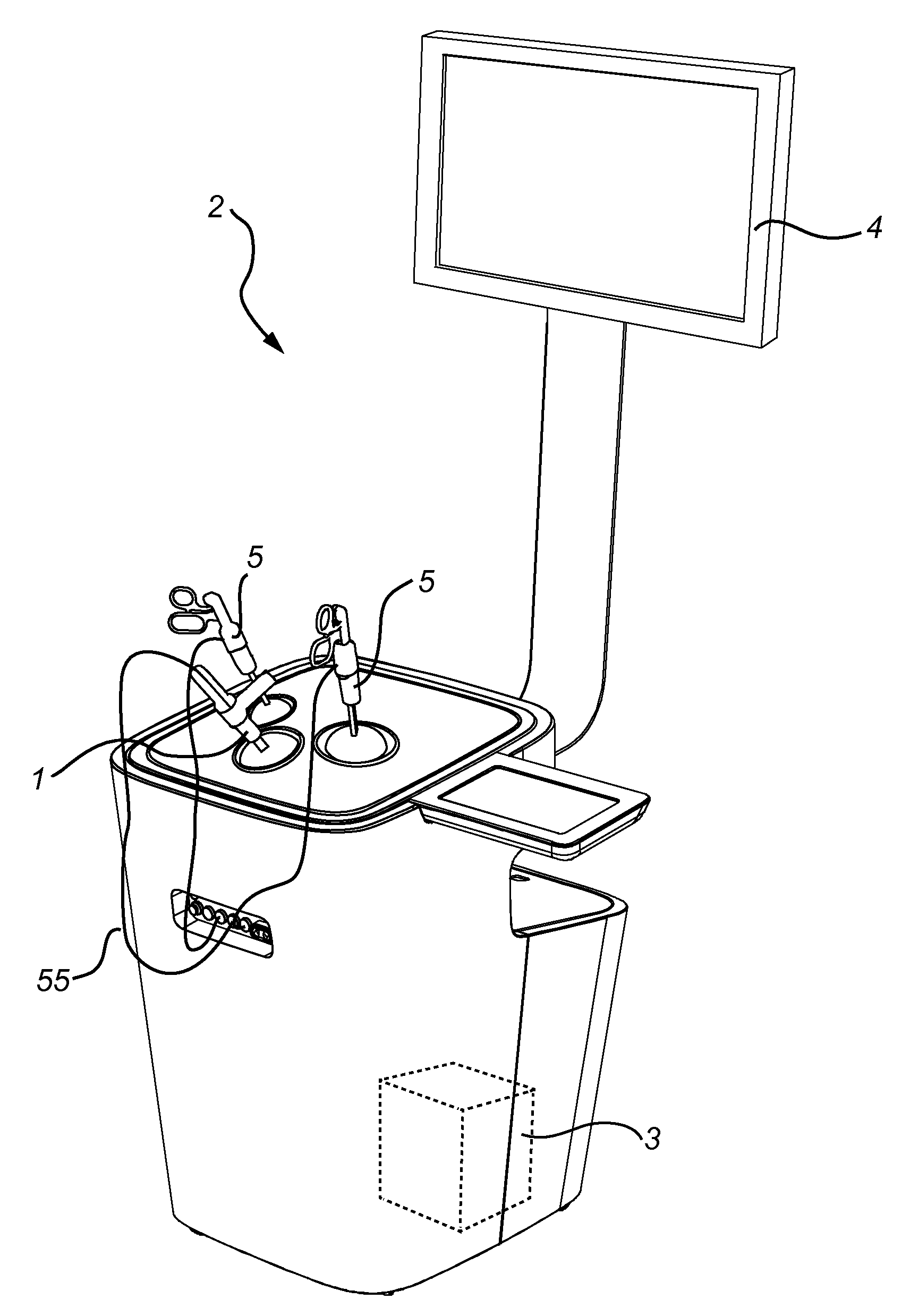
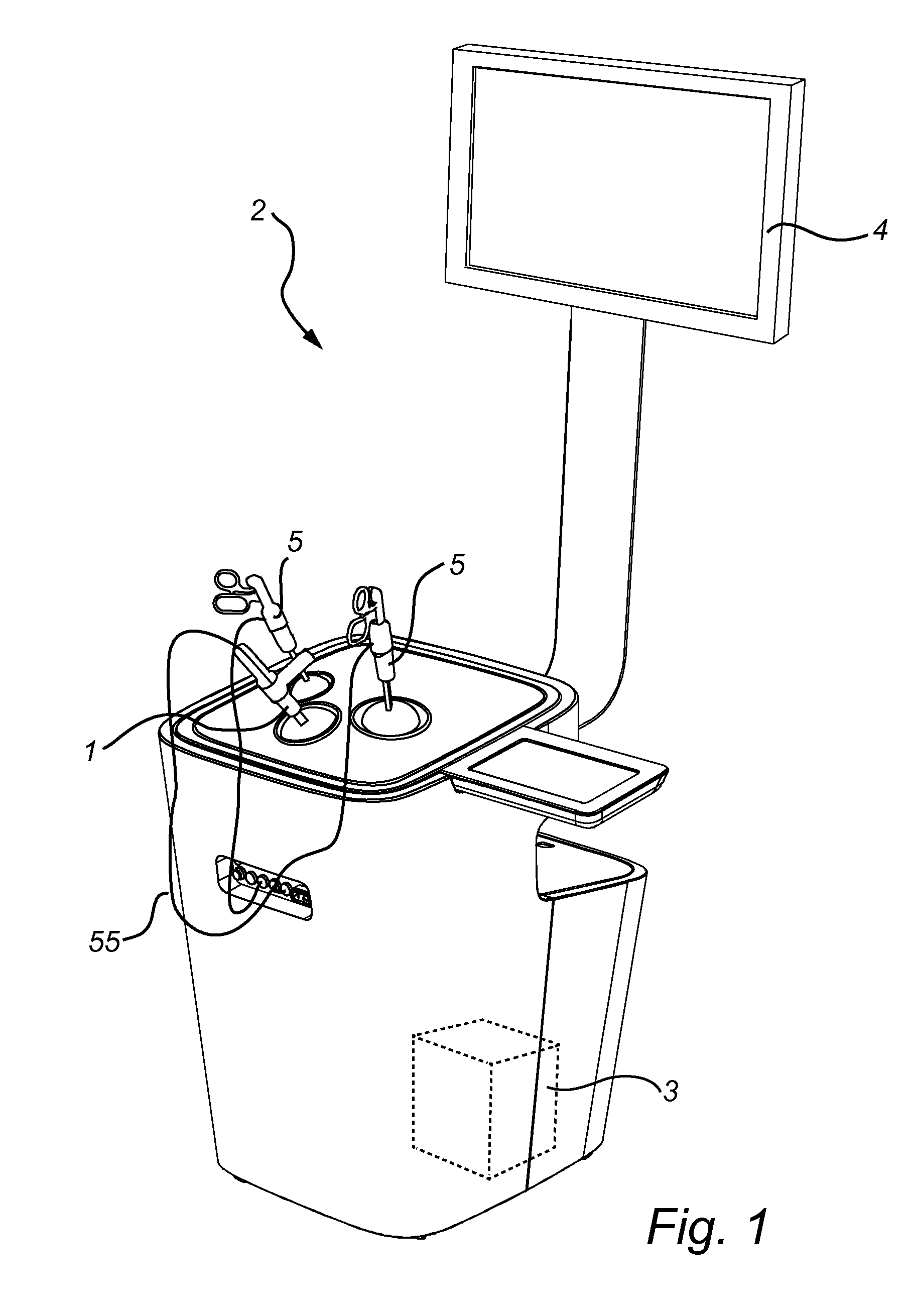
[0021]FIG. 1 shows a simulation system 2 implementing a user interface device 1 according to an embodiment of the present invention. A user interface device according to the present invention may be implemented in many other types of simulation systems, including non-surgical simulation systems. In the illustrated case, the simulation system 2 is a surgical simulation system and comprises a processing unit 3 running simulation software for simulating a surgical procedure, and a display 4 for displaying a visualization of the simulated procedure to a user. The system further has three user interface devices 1, 5 connected to the processing unit 3. Two of these, 5, are adapted to simulate surgical instruments operated by a physician inside a human body. The third interface device 1 is adapted to simulate a camera provided inside the human body, and arranged to acquire visual output from the surgical procedure, In use, the three interfaces are used by a user, typically a physician trai...


PUM


Abstract

A user interface device (1) comprising a frame (11) with a support (15) and a suspension portion (16) rotatable around a first axis (A). Further comprising a camera simulator (10) having a rigid shaft (21) with a primary extension along a longitudinal axis (C), being suspended by the suspension portion (16) so that it can translate along the longitudinal axis (C). A first rotational sensor (25) arranged to detect rotation of the suspension portion (16) around the first axis (A) by a guiding surface (18a) arranged at a distance from the first axis (A), and a first roller (30) arranged between the axis (A) and the guiding surface (18a) to rotate when the suspension portion (16) is rotated around the first axis (A) wherein the first rotational sensor (25) is arranged to detect rotation of the first roller (30). This solution enables satisfactory measured resolution at more reasonable price.

Description

FIELD OF THE INVENTION[0001]The present invention relates generally to a user interface device for a surgical simulation system, and more specifically to an interface for a camera simulator.BACKGROUND OF THE INVENTION[0002]In recent years, systems for surgical simulations have become increasingly more used, in order to train physicians various surgical procedures without putting live patients at risk. In particular in the field of minimally-invasive surgery, such as laparoscopy, endoscopy, colonoscopy, etc., such simulation systems have gained significant acceptance. During minimal-invasive surgery the physician typically relies on an image on a screen rather than on an actual view of the patient, and with powerful image rendering available today, such an image can be simulated with a very high degree of realism.[0003]During actual surgery this image is provided by a camera. The optics of such a camera is commonly mounted on the chamfered end of a shaft to enable a field of view tha...

Claims


Application Information

Patent Timeline
IPC IPC(8): G09B23/28
CPCG09B23/28G09B23/286G09B23/285
Inventor LARSSON, ANDERSJOHANSSONNYSTROM, MATTIAS
Owner SURGICAL SCI SWEDEN
Learn More