Solid-state electrolytic capacitor with improved metallic anode and method for manufacturing the same

Active Publication Date: 2016-04-28
APAQ TECH
View PDF2 Cites 2 Cited by
  • Summary
  • Abstract
  • Description
  • Claims
  • Application Information

AI Technical Summary

Benefits of technology

[0008]The object of the instant disclosure is to provide a solid-state electrolytic capacitor with improved metallic anode and a method for manufacturing the same. The instant solid-state electrolytic capacitor is

Problems solved by technology

However, due to the thick anode portion of each capacitor unit almost always result in low welding quality and low welding success rate.
Further, the maximum number of the stacked capacitor units is limited by the thick anode portion of each capacitor unit.
Moreover, in the welding process, molten aluminum can be readily

Method used


Image

  • Solid-state electrolytic capacitor with improved metallic anode and method for manufacturing the same
  • Solid-state electrolytic capacitor with improved metallic anode and method for manufacturing the same
  • Solid-state electrolytic capacitor with improved metallic anode and method for manufacturing the same

Examples


first embodiment

The First Embodiment

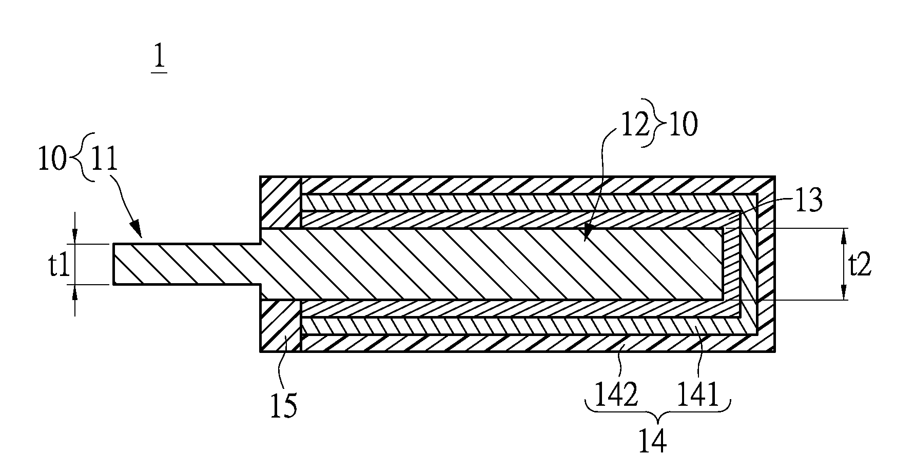
[0024]Please refer to FIG. 1, which shows a cross-sectional view of a solid-state electrolytic capacitor with improved metallic anode in accordance to the first embodiment of the instant disclosure. The solid-state electrolytic capacitor 1 mainly includes a substrate layer 10, a conductive polymer layer 13, and an electrode layer 14. The substrate layer 10 has an anode part 11 and a cathode part 12 separated by an insulating layer 15. The anode part 11 and the cathode parts 12 defining an anode region and a cathode region, respectively, on the solid-state electrolytic capacitor 1. The conductive polymer layer 13 is formed on a portion of the cathode part 12 of the substrate layer 10. The electrode layer 14 is formed to cover the conductive polymer layer 13. Please note that the anode part 11 has a thinner thickness t1 than a thickness t2 of the cathode part 12.

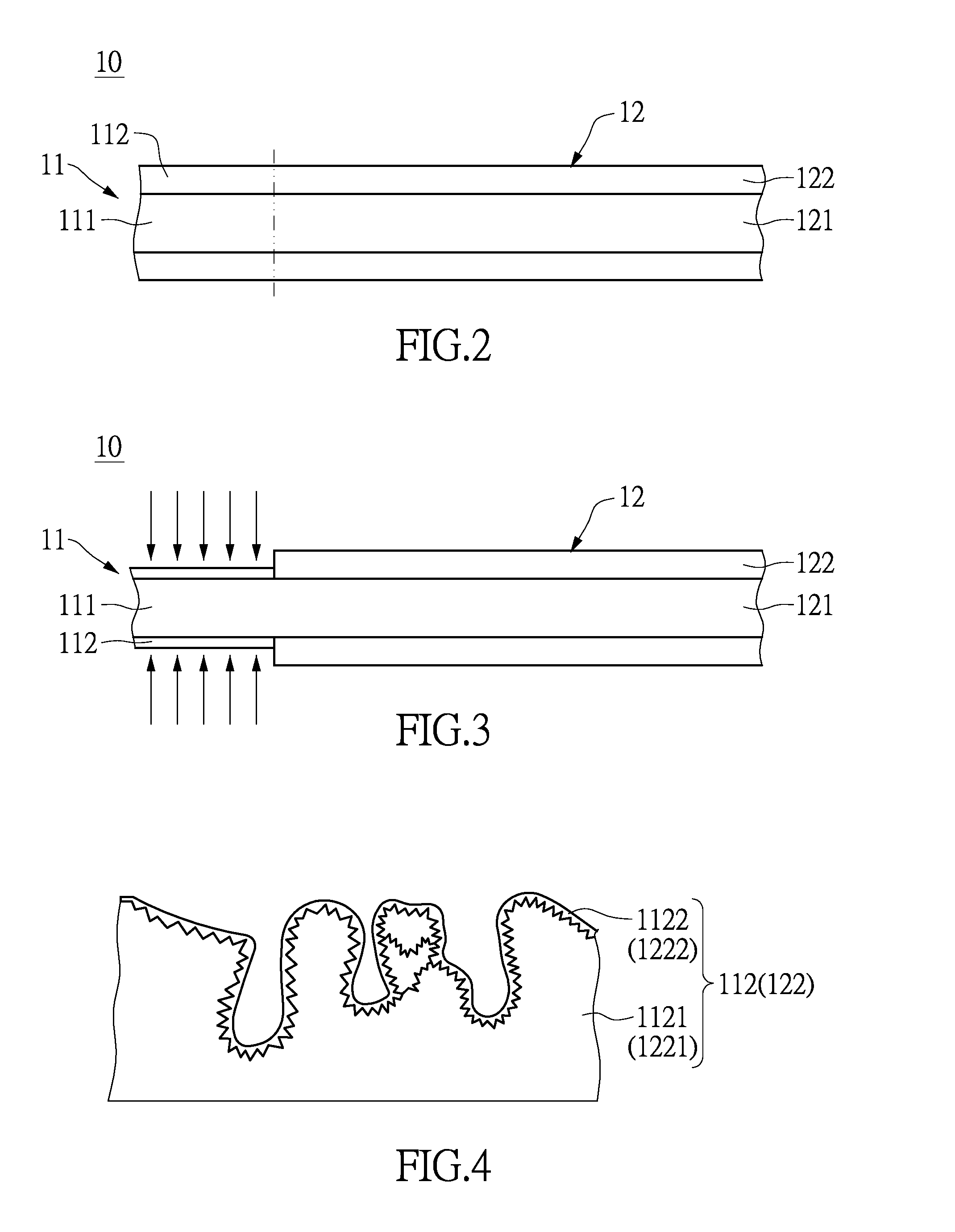
[0025]Please refer to FIGS. 2 and 3. To provide further explanation, the anode part 11 of the substrate ...

second embodiment

The Second Embodiment

[0029]Please refer to FIGS. 1 and 5. For the second embodiment, the anode part 11 of substrate layer 10 consists only of the first metallic core body 111. The cathode part 12 of substrate layer 10 includes a second metallic core body 121 and two second corrosion layers 122 formed on two opposite surfaces of the second metallic core body 121. The difference between the second embodiment and the first embodiment is that the first corrosion layers 112 and a portion of the first metallic core body 111 of the anode part 111 are removed after thinning. Thus, the anode part 11 has a thinner thickness t1 than a thickness t2 of the cathode part 12.

[0030]The structural features of the solid-state electrolytic capacitor 1 are mentioned above. Referring now to FIG. 6, the following will describe a method for manufacturing the solid-state electrolytic capacitor 1.

[0031]The method firstly provides a substrate layer 10 having an anode part 11 and a cathode part 12 (step S100)....


PUM


Abstract

The instant disclosure relates to a solid electrolytic capacitor with improved metallic anode and a method for manufacturing the same. The solid electrolytic capacitor includes a substrate layer, a conductive polymer layer and an electrode layer. The substrate layer has a cathode portion and an anode portion having a smaller thickness than the cathode portion. The conductive polymer layer is formed to cover the cathode portion of the substrate layer. The electrode layer is formed to cover the conductive polymer layer. Therefore, the instant solid electrolytic capacitor can be applied to a packing process, and welding success yield rate can be improved.

Description

BACKGROUND OF THE INVENTION[0001]1. Field of the Invention[0002]The instant disclosure relates to a solid-state electrolytic capacitor; in particular, to a solid-state electrolytic capacitor with improved metallic anode, and to a method for manufacturing the same.[0003]2. Description of Related Art[0004]The capacitor is an indispensable element in many electronic products. Various applications of capacitors include home appliances, computer motherboards and peripherals, power supplies, communication products and automobiles. The capacitors such as solid electrolytic capacitors are mainly used to provide filtering, bypassing, rectifying, coupling, blocking or transforming function. With the rapid advancement of semiconductor processing technology, packaged electronic products follows the trend of miniaturization, high electrical performance, multi-function, high reliability, and RoHS Compliance. The wet electrolytic capacitor cannot accommodate the requirements of the electronic prod...

Claims


Application Information

Patent Timeline
IPC IPC(8): H01G9/048H01G9/00H01G9/045H01G9/15H01G9/042H01G9/052
CPCH01G9/048H01G9/042H01G9/0029H01G9/045H01G9/15H01G9/052
Inventor CHIU, CHI-HAOCHEN, MING-TSUNGSUNG, CHAI-CHING
Owner APAQ TECH
Why Eureka
Try Eureka