Video laryngoscope and video laryngoscope insertion section

a technology of which is applied in the field of video laryngoscope and insertion section of video laryngoscope, can solve the problems of unsatisfactory, user's application of unnecessary force, and lack of sufficient room to pass the endotracheal tube, so as to reduce the contact surface area and reduce the risk of tissue damag

Active Publication Date: 2016-05-05
COVIDIEN AG
View PDF2 Cites 14 Cited by
  • Summary
  • Abstract
  • Description
  • Claims
  • Application Information

AI Technical Summary

Benefits of technology

[0027]By avoiding excessive longitudinal curvature in the intermediate region, the insertion section is easy to introduce into a subject. This contrasts with insertion sections having a discrete corner, or elbow, in the inferior surface.
[0075]The microscopically rough regions will have a reduced contact surface area with a subject's tissues compared to a completely smooth surface, reducing the risk of damage to a subject's tissues during intubation. Typically, the microscopically rough regions appear frosted. This is due to light scattering by the microscopically rough regions. The smooth surface of the viewing port need not be flat and indeed typically comprises one or more surface features, such as a prism.

Problems solved by technology

However, where there are anomalies within the oral cavity of the subject, or where an effective view of the larynx cannot be achieved with a direct view blade such as in instances where the subject's head and neck are not able to be moved to attain a direct line of sight of the larynx, it is often necessary to use an insertion section with a greater curvature to allow the blade to be inserted into the oral cavity.
This can often result in a lack of sufficient room to pass the endotracheal tube into the trachea as the tip of the insertion section is too anterior in the subject's mouth in contrast to when the tip of the insertion section is placed correctly fully into the vallecular to raise the epiglottis.
This can cause a user to apply unnecessary force to try to make more room to pass the tube, or to position the tube more anteriorly.
However, this is not satisfactory as there is a significant variation in the correct depth of insertion of an insertion section between subjects within each group, and so a single indicator line is not of practical assistance.
Friction between an insertion section and tissues can cause trauma and affect the safety of an intubation.
For example, the subject's lips may stick to the insertion section and become dragged over the lower incisors causing trauma and bleeding.

Method used


Image

  • Video laryngoscope and video laryngoscope insertion section
  • Video laryngoscope and video laryngoscope insertion section
  • Video laryngoscope and video laryngoscope insertion section

Examples


Embodiment Construction

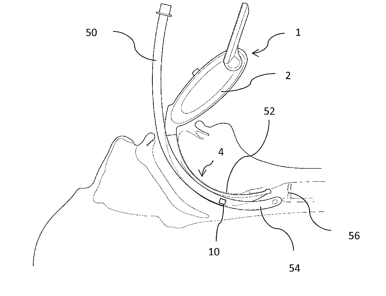
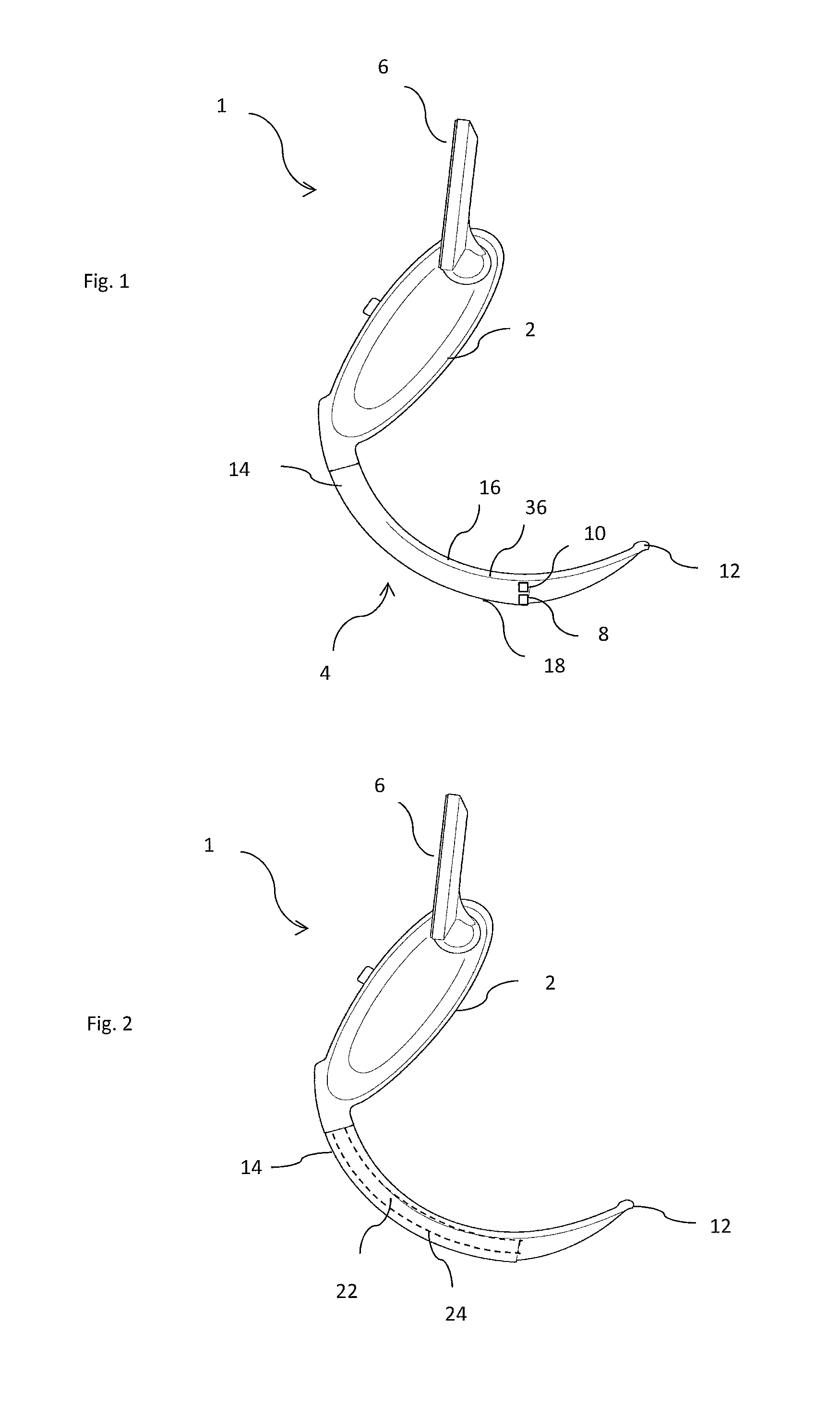
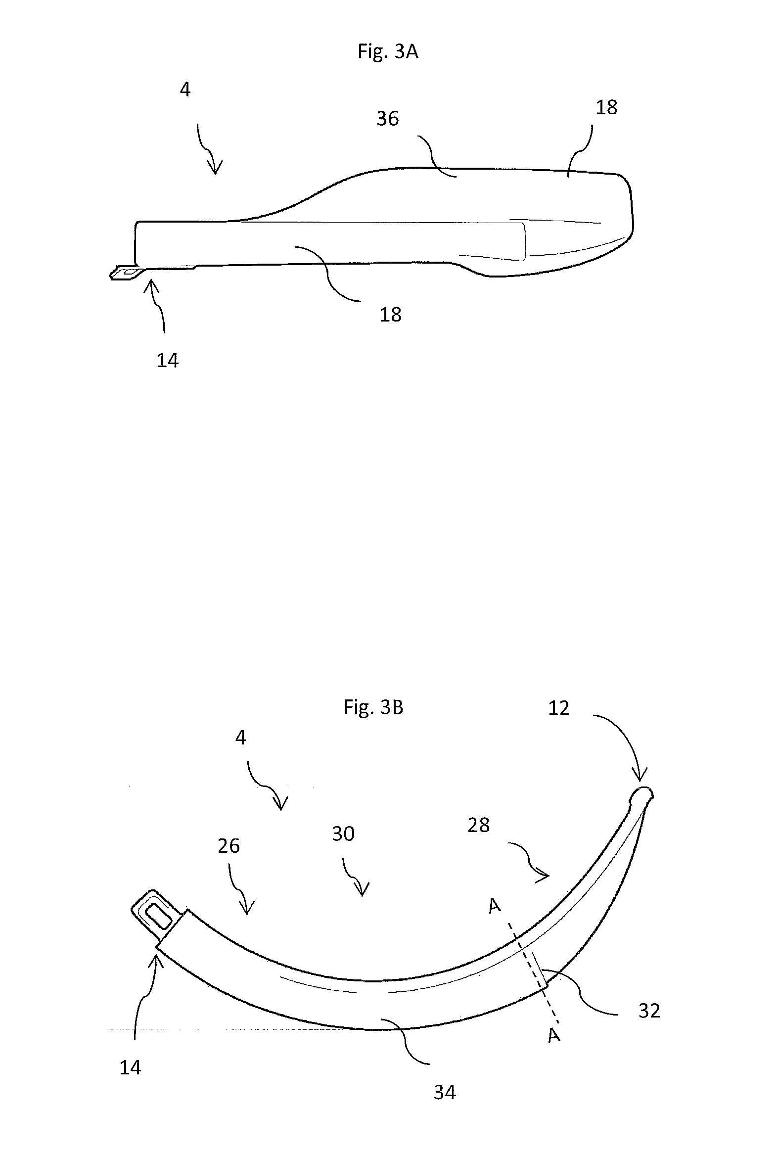
[0112]With reference to FIGS. 1 to 12, a video laryngoscope 1 comprises a handle 2 and an elongate insertion section 4 which extends from the handle. The handle has a display 6 for showing video images obtained by a camera 8, using light obtained from an LED light source 10. The camera is located in the superior half of the insertion section. The insertion section has a distal end 12 and an opposite proximal end 14. The insertion section has an inferior surface 16 which faces towards a subject's tongue in use and an opposite superior surface 18. An elongate member 34 extends along the insertion section longitudinally from the proximal end and a flange 36 extends laterally from and distally of the elongate member and, along with the inferior surface of the elongate member defines the inferior surface of the insertion section.

[0113]With reference to FIG. 2, the handle has an elongate insertion section retaining member 22 extending therefrom, and the insertion section has an elongate c...


PUM


Abstract

A video laryngoscope and elongate laryngoscope insertion section for a video laryngoscope, comprising a viewing port through which an imaging device within the insertion section can obtain images of a larynx, the insertion section extending between a distal end for insertion into a subject and an opposite proximal end, and having an inferior surface and an opposed superior surface, wherein the insertion section comprises a proximal region where the insertion section extends through a subject's teeth in use, a distal region extending to the distal end and an intermediate region therebetween, wherein the inferior surface of the insertion section comprises or consists of a curved region which extends from the proximal region through the intermediate region to the distal region, wherein the curved region of the inferior surface is continuously longitudinally curved along the length of the longitudinally curved region and wherein the longitudinal curvature of the curved region of the inferior surface varies in the intermediate region. Markings on an elongate laryngoscope insertion can be used to monitor depth of insertion and to indicate a path by which an endotracheal tube should be inserted.

Description

FIELD OF THE INVENTION[0001]The invention relates to the field of video laryngoscopes and insertion sections for video laryngoscopes.BACKGROUND TO THE INVENTION[0002]Laryngoscopes are medical devices in common use in oral and tracheal medical procedures, which may be used to obtain a view of the glottis or larynx, or to manipulate the tongue, glottis or larynx in order to facilitate insertion of endotracheal tubes or other instruments such as endoscopes, which may be separate pieces of equipment, or may be integral to a laryngoscope.[0003]Laryngoscopes comprise insertion sections, which are the elongate part of a laryngoscope which extends into a subject's oral cavity during intubation. Insertion sections may be removably attachable to a laryngoscope body or integral parts of laryngoscopes or themselves function as laryngoscopes. As well as an insertion section, laryngoscopes typically comprises a handle which is usually elongate and which may be arranged at an angle to the proximal...

Claims


Application Information

Patent Timeline
Patent Type & Authority Applications(United States)
IPC IPC(8): A61B1/00A61B1/04A61B1/267
CPCA61B1/00064A61B1/267A61B1/00096A61B1/00045A61B1/00075A61B1/04A61B1/00142
Inventor MCGRATH, MATTHEW JOHN ROSSINGLIS, PETER DOUGLAS COLIN
Owner COVIDIEN AG
Why Eureka
Try Eureka